Amana AEP222VA Installation Instruction - Page 7
Warning
 |
View all Amana AEP222VA manuals
Add to My Manuals
Save this manual to your list of manuals |
Page 7 highlights
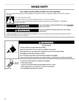
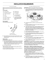
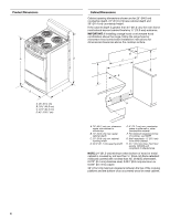
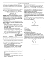
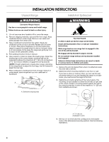
Floor Mounting 5. Using the Phillips screwdriver, mount anti-tip bracket to the wall or floor with the two #12 x 1⁵⁄₈" screws provided. 6. Move range close enough to opening to allow for final gas and electrical connections. Remove shipping base, cardboard or hardboard from under range. 7. Move range into its final location, making sure rear leveling leg slides into anti-tip bracket. Rear position Wall Mounting Front position Diagonal (2 options) 8. Move range forward onto shipping base, cardboard or hardboard to continue installing the range using the following installation instructions. Power Supply Cord Electrical Connection Direct Wire WARNING WARNING Electrical Shock Hazard Disconnect power before servicing. Use a new 40 amp power supply cord. Plug into a grounded outlet. Failure to follow these instructions can result in death, fire, or electrical shock. Electrical Shock Hazard Disconnect power before servicing. Use 8 gauge copper or 6 gauge aluminum wire. Electrically ground range. Failure to follow these instructions can result in death, fire, or electrical shock. 1. Disconnect power 2. Remove the terminal block cover screws located on the back of the range. Pull cover down and toward you to remove cover. 3. Add strain relief. Style 1: Power supply cord strain relief ■ Assemble a UL listed strain relief in the opening. A B A. Hold-down screws B. Terminal block cover A B A. UL listed strain relief - large opening B. Small opening ■ Feed the power supply cord through the strain relief on the cord/conduit plate on bottom of range. Allow enough slack to easily attach the wiring to the terminal block. 7
-
 1
1 -
 2
2 -
 3
3 -
 4
4 -
 5
5 -
 6
6 -
 7
7 -
 8
8 -
 9
9 -
 10
10 -
 11
11 -
 12
12
 |
 |
