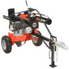
Ariens 34-Ton Log Splitter Owners Manual - Page 9
Attach Control Lever, Check Tire Pressure, Purge Hydraulic System and Add, Hydraulic Oil - parts
 |
View all Ariens 34-Ton Log Splitter manuals
Add to My Manuals
Save this manual to your list of manuals |
Page 9 highlights
Secure with hex bolts and nuts. Figure 5 Attach Control Lever (Figure 6) 1. Remove the clevis pin (1) and cotter pin (2) from the control valve. 2. Rotate the control lever up and reinsert the clevis pin. 3. Insert cotter pin back into clevis pin and spread tangs outward. 2 1 Rotate lever forward and into position. Install clevis pin and cotter pin. Figure 6 Check Tire Pressure CAUTION: Avoid injury! Explosive separation of tire and rim parts is possible when they are serviced incorrectly: • Do not attempt to mount a tire without the proper equipment and experience to perform the job. • Do not inflate the tires above the recommended pressure. • Do not weld or heat a wheel and tire assembly. Heat can cause an increase in air pressure resulting in an explosion. Welding can structurally weaken or deform the wheel. • Do not stand in front or over the tire assembly when inflating. Use a clip-on chuck and extension hose long enough to allow you to stand to one side. See SPECIFICATIONS on page 21 for tire pressure. Purge Hydraulic System and Add Hydraulic Oil IMPORTANT: ADD OIL BEFORE OPERATING! Add hydraulic oil to operating level before first use. The system may take up to two gallons. See HYDRAULIC OIL SYSTEM on page 18. Do not overfill. Before first use or after hydraulic system maintenance: 1. Purge any air in the system by cycling the hydraulic cylinder (see Purge Air From Hydraulic System on page 19). 2. Add hydraulic oil as necessary to bring system to operating level. NOTE: Some hydraulic fluid may overflow from the cap/breather as the system warms up and the fluid expands. Do not operate the unit without the proper amount of oil in the reservoir. Fill Engine Fuel Tank Fill fuel tank. DO NOT OVERFILL! See FILLING FUEL TANK on page 14 Check Function of All Controls See OPERATION on page 11. GB - 9
-
 1
1 -
2
-
3
-
 4
4 -
 5
5 -
 6
6 -
 7
7 -
 8
8 -
 9
9 -
 10
10 -
 11
11 -
 12
12 -
 13
13 -
 14
14 -
15
-
16
-
17
-
18
-
19
-
20
-
21
-
22
-
23
-
24
-
25
-
26
-
27
-
28
 |
 |
