Asus A7V8X-X A7V8X-X User Manual
Asus A7V8X-X Manual
 |
View all Asus A7V8X-X manuals
Add to My Manuals
Save this manual to your list of manuals |
Asus A7V8X-X manual content summary:
- Asus A7V8X-X | A7V8X-X User Manual - Page 1
Motherboard A7V8X-X User Guide - Asus A7V8X-X | A7V8X-X User Manual - Page 2
Product warranty or service will not be extended if: (1) the product is repaired, modified or altered, unless such repair, modification of alteration is authorized in writing by ASUS; or (2) the serial number of the product is defaced or missing. ASUS PROVIDES THIS MANUAL "AS IS" WITHOUT WARRANTY - Asus A7V8X-X | A7V8X-X User Manual - Page 3
for this motherboard 1-12 1.10.3 AGP slot 1-13 1.11 Jumpers 1-13 1.12 Connectors 1-15 Chapter 2: BIOS information 2.1 Managing and updating your BIOS 2-2 2.1.1 Using ASUS EZ Flash to update the BIOS 2-2 2.1.2 Using AFLASH to update the BIOS 2-4 2.1.3 CrashFree BIOS feature 2-7 2.2 BIOS Setup - Asus A7V8X-X | A7V8X-X User Manual - Page 4
2-24 2.6 Boot Menu 2-25 2.7 Exit Menu 2-26 Chapter 3: Software support 3.1 Install an operating system 3-2 3.2 Support CD information 3-2 3.2.1 Running the support CD 3-2 3.2.2 Drivers menu 3-3 3.2.3 Utilities menu 3-3 3.2.4 ASUS Contact Information 3-4 3.2.5 Multi-channel audio feature - Asus A7V8X-X | A7V8X-X User Manual - Page 5
and, if not installed and used in accordance with manufacturer's instructions, may cause harmful interference to radio communications. However, there is reception, which can be determined by turning the equipment off and on, the user is encouraged to try to correct the interference by one or more of - Asus A7V8X-X | A7V8X-X User Manual - Page 6
signal cables from the motherboard, ensure that all service technician or your retailer. Operation safety • Before installing the motherboard and adding devices on it, carefully read all the manuals screws, and staples away from connectors, slots, sockets and circuitry. • Avoid dust, humidity, and - Asus A7V8X-X | A7V8X-X User Manual - Page 7
this guide To make sure that you perform certain tasks properly, take note of the following symbols used throughout this manual. WARNING updates. 1. ASUS Websites The ASUS websites worldwide provide updated information on ASUS hardware and software products. The ASUS websites are listed in the ASUS - Asus A7V8X-X | A7V8X-X User Manual - Page 8
CA 94560, USA General Fax: +1-510-608-4555 General Email: [email protected] Technical Support Support Fax: +1-510-608-4555 General Support: +1-502-933-8713 Web Site: www.asus.com Support Email: [email protected] ASUS COMPUTER GmbH (Germany and Austria) Address: Harkortstr. 25, 40880 Ratingen - Asus A7V8X-X | A7V8X-X User Manual - Page 9
A7V8X-X specifications summary CPU Chipset Front Side Bus (FSB) Memory Expansion slots IDE Audio (optional) LAN (optional) USB 2.0 Special Features Back Panel I/O Ports Internal I/O Connectors Socket A for AMD Barton/Thoroughbred/Athlon XP/Athlon/ Duron 2.25+ GHz CPU Northbridge: VIA KT400 - Asus A7V8X-X | A7V8X-X User Manual - Page 10
, Chassis Intrusion Form Factor ATX form factor: 12 in x 9.6 in (30.5 cm x 24.5 cm) Support CD contents Device drivers ASUS PC Probe Trend Microtm PC-cillin 2002 anti-virus software ASUS LiveUpdate Utility Accessories User's manual Support CD 1 x UltraDMA 133/100/66 cable FDD cable I/O shield - Asus A7V8X-X | A7V8X-X User Manual - Page 11
Chapter 1 This chapter gives information about the ASUS A7V8X-X motherboard that came with the system.This chapter includes the motherboard layout, jumper settings, and connector locations. Motherboard Info ASUS A7V8X-X Motherboard 1-1 - Asus A7V8X-X | A7V8X-X User Manual - Page 12
ASUS A7V8X-X package for the following items. ASUS A7V8X-X motherboard ATX form factor: 12 in x 9.6 in (30.5 cm x 24.5 cm) ASUS A7V8X-X series support CD 1 pc. 80-conductor ribbon cable for UltraDMA/66/100/133 IDE drives Ribbon cable for a 3.5-inch floppy drive Bag of extra jumper caps User Guide - Asus A7V8X-X | A7V8X-X User Manual - Page 13
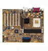
you install the motherboard, learn about its major components and available features to facilitate the installation and future upgrades. Refer to the succeeding pages for the component descriptions. 1 2 3 4 14 13 12 11 15 10 9 16 17 25 24 23 ASUS A7V8X-X Motherboard 22 21 5 6 7 8 18 - Asus A7V8X-X | A7V8X-X User Manual - Page 14
Core specifications 1 North bridge controller. The VIA® KT400 supports AGP 8X mode, 333/ 266/200MHz Front Side Bus, and the latest 400/333/266/200MHz 64-bit memory bus. 2 CPU socket. Socket 462 (Socket A) surface mount, Zero Insertion Force (ZIF) socket for the AMD Barton/Thoroughbred/Athlon XP - Asus A7V8X-X | A7V8X-X User Manual - Page 15
sound, S/PDIF interface, AUX and Line In stereo inputs, integrated headphone amplifier, greater than 90dB dynamic range. (on audio models only) 13 LAN PHY. This Realtek RTL8201BL LAN PHY supports your local area networking needs. (on LAN model only) 14 AGP slot. This Accelerated Graphics Port (AGP - Asus A7V8X-X | A7V8X-X User Manual - Page 16
restore the CPU default setting for each parameter. CrashFree BIOS CrashFree BIOS allows users to restore BIOS data from a floppy diskette even when BIOS code and data are corrupted during upgrade or invaded by a virus. Unlike other competing vendors' products, ASUS motherboards now enable users to - Asus A7V8X-X | A7V8X-X User Manual - Page 17
:Line Out Below:Mic In AUX CD LAN PHY FP_AUDIO Audio Codec MDC VIA KT400 Chipset Accelerated Graphics Port (AGP) 01 23 45 PCI Slot 1 A7V8X-X PCI Slot 2 PCI Slot 3 PCI Slot 4 PCI Slot 5 ® PCI Slot 6 VIA VT8235 Chipset CR2032 3V Lithium Cell CMOS Power CLRTC Super I/O GAME USBPW56 USB56 - Asus A7V8X-X | A7V8X-X User Manual - Page 18
and unplug the power cable before removing or plugging in any motherboard component. A7V8X-X ® A7V8X-X Onboard LED SB_PWR ON Standby Power OFF Powered Off Install only 1.5V AGP cards on this motherboard to prevent damage to your AGP card or motherboard. 1-8 Chapter 1: Motherboard Information - Asus A7V8X-X | A7V8X-X User Manual - Page 19
as indicated in the image below. 1.7.2 Screw holes Place nine (9) screws into the holes indicated by circles to secure the motherboard to the chassis. Do not overtighten the screws! Doing so may damage the motherboard. Place this side towards the rear of the chassis ASUS A7V8X-X Motherboard 1-9 - Asus A7V8X-X | A7V8X-X User Manual - Page 20
(CPU) The motherboard provides a Socket A (462) for CPU installation. AMD processors offer gigahertz speeds to support all the latest computing platforms and applications. The A7V8X-X supports AthlonTM XP, AthlonTM, Barton™ and DuronTM processors. A7V8X-X ® A7V8X-X Socket A AMD™ CPU CPU NOTCH - Asus A7V8X-X | A7V8X-X User Manual - Page 21
installing the expansion card, configure the card by adjusting the software settings. 1. Turn on the system and change the necessary BIOS settings, if any. 2. Assign an IRQ to the card. Refer to the tables below. 3. Install the software drivers for the expansion card. ASUS A7V8X-X Motherboard 1-11 - Asus A7V8X-X | A7V8X-X User Manual - Page 22
.3 AGP slot This motherboard has an Accelerated Graphics Port (AGP) slot that supports +1.5V AGP cards only. When you buy an AGP card, make sure that you ask for one with +1.5V specification. Note the notches on the card golden fingers to ensure that they fit the AGP slot on your motherboard. A7V8X - Asus A7V8X-X | A7V8X-X User Manual - Page 23
adjust the CPU VCORE through the BIOS Setup. OVER_VOLT 12 23 Enable Disable (Default) A7V8X-X ® A7V8X-X OVER_VOLT Setting Setting to a very high core voltage may cause permanent damage to the CPU. It is recommended that you keep the default setting (Disable). ASUS A7V8X-X Motherboard 1-13 - Asus A7V8X-X | A7V8X-X User Manual - Page 24
3 seconds. 4. Re-install the battery. 5. Plug the power cord and turn ON the computer. 6. Hold down the key during the boot process and enter BIOS setup to re-enter data. CLRTC A7V8X-X ® 2 1 Clear CMOS 3 2 Normal (Default) A7V8X-X Clear RTC RAM Setting 4. Keyboard power (3-pin KBPWR - Asus A7V8X-X | A7V8X-X User Manual - Page 25
. Connect a 2-port USB connector set to a USB header and mount the USB bracket to an open slot in the chassis. USB+6V USB_P6USB_P6+ GND NC A7V8X-X ® USB56 1 USB+5V USB_P5USB_P5+ GND A7V8X-X USB 2.0 Header The USB/GAME module is not included in the package. ASUS A7V8X-X Motherboard 1-15 - Asus A7V8X-X | A7V8X-X User Manual - Page 26
BIOS supports specific A7V8X-X IDE Connectors PIN 1 4. MDC header (10-1 pin MDC) This ASUS proprietary modem header accomodates an optional modem module. MODEM_IN AC97_SYNC AC97_SDIN1 GND AC97_BITCLK A7V8X-X 1-16 ® A7V8X-X MDC Header GND +3VSB AC97_RST# AC97_SDOUT MDC Chapter 1: Motherboard - Asus A7V8X-X | A7V8X-X User Manual - Page 27
-X PIN 1 ® NOTE: Orient the red markings on the floppy ribbon cable to PIN 1. A7V8X-X Floppy Disk Drive Connector 6. CPU and Chassis Fan Connectors (3-pin CPU_FAN, CHA_FAN) The two fan connectors support cooling fans of 350mA (4.2 Watts) or a total of 1A (12W) at +12V. Orient the fans so that the - Asus A7V8X-X | A7V8X-X User Manual - Page 28
connectors (4-pin AUX, CD) These connectors allow you to receive stereo audio input from sound sources such as a CD-ROM, TV tuner, or MPEG card. AUX (White) CD (Black) A7V8X-X ® A7V8X-X Internal Audio Connectors 8. Front panel audio connectors (10-1 pin FP_AUDIO) This is an interface for the Intel - Asus A7V8X-X | A7V8X-X User Manual - Page 29
a joystick or a game pad for playing games, and MIDI devices for playing or editing audio files. +5V J1B2 J1CY GND GND J1CX J1B1 +5V A7V8X-X ® A7V8X-X Game Connector GAME The USB/GAME module is not included in the package. ASUS A7V8X-X Motherboard MIDI_IN J2B2 J2CY MIDI_OUT J2CX J2B1 +5V 1-19 - Asus A7V8X-X | A7V8X-X User Manual - Page 30
PWR Ground Reset Ground A7V8X-X ® A7V8X-X System Panel Connectors IDE_LED beeps and warnings. • System Management Interrupt Lead (2-pin SMI) This 2-pin connector allows you to manually or ON and SOFT OFF, depending on the BIOS or OS settings. Pressing the power switch while Motherboard Information - Asus A7V8X-X | A7V8X-X User Manual - Page 31
Chapter 2 This chapter gives information about the ASUS A7V8X-X Binary Input/Output System (BIOS).This chapter includes updating the BIOS using the ASUS AFLASH BIOS that is bundled with the support CD. BIOS Information ASUS A7V8X-X Motherboard 2-1 - Asus A7V8X-X | A7V8X-X User Manual - Page 32
of the motherboard's original BIOS to a bootable floppy disk in case you need to reinstall the original BIOS later. 2.1.1 Using ASUS EZ Flash to update the BIOS The ASUS EZ Flash feature allows you to easily update the BIOS without having to go through the long process of booting from a diskette - Asus A7V8X-X | A7V8X-X User Manual - Page 33
_ (Y/N)? _ DO NOT shutdown or reset the system while updating the BIOS boot block area! Doing so may cause system boot failure. 8. When the update process is done, the message, "Press a key to reboot" appears. Press any key to reboot the system with the new BIOS. ASUS A7V8X-X Motherboard 2-3 - Asus A7V8X-X | A7V8X-X User Manual - Page 34
AFLASH.EXE is a Flash Memory Writer utility that updates the BIOS by uploading a new BIOS file to the programmable flash ROM on the motherboard. This file works only in DOS mode. To determine the BIOS version of your motherboard, check the last four numbers of the code displayed on the upper left - Asus A7V8X-X | A7V8X-X User Manual - Page 35
more problems with the motherboard! 1. Download an updated ASUS BIOS file from the Internet (WWW or FTP) (see ASUS CONTACT INFORMATION on page x for details) and save to the boot floppy disk you created earlier. 2. Boot from the floppy disk. 3. At the "A:\" prompt, type AFLASH and then press - Asus A7V8X-X | A7V8X-X User Manual - Page 36
while updating the BIOS. This may cause boot problems. Just repeat the process, and if the problem persists, load the original BIOS file you saved to the boot disk. If the Flash Memory Writer utility is not able to successfully update a complete BIOS file, call the ASUS service center for support - Asus A7V8X-X | A7V8X-X User Manual - Page 37
the failure. To update the BIOS: 1. Turn on the computer, and when prompted, place the bootable floppy disk into the floppy drive, so that the computer boots from the floppy disk. 2. Follow the BIOS update procedure in section "2.1.2 Using AFLASH to update the BIOS." ASUS A7V8X-X Motherboard 2-7 - Asus A7V8X-X | A7V8X-X User Manual - Page 38
BIOS Setup program so that the computer can recognize these changes and record them in the CMOS RAM of the EEPROM. The EEPROM on the motherboard BIOS software is constantly being updated, the following BIOS setup configure and enable Power Management features. BOOT Use this menu to configure the - Asus A7V8X-X | A7V8X-X User Manual - Page 39
the Item Specific Help window, the BIOS setup window. Use and or the up and down arrow keys to scroll through the entire help document. Press to display the first page, press to go to the last page. To exit the help window, press or . ASUS A7V8X-X Motherboard - Asus A7V8X-X | A7V8X-X User Manual - Page 40
appear in the Item Specific Help window located to the right of each menu. This window displays the help text for the currently highlighted field. 2.3 Main Menu When you enter the Setup program, the > + keys to move between the hour, minute, and second fields. 2-10 Chapter 2: BIOS Information - Asus A7V8X-X | A7V8X-X User Manual - Page 41
cell battery. If you need to erase the CMOS RAM, unplug the all the power cables and remove the button cell battery. Re-install the battery after about 2 seconds, then power up the system. Refer to section "2.1 Managing and updating your BIOS" on how to update the BIOS. ASUS A7V8X-X Motherboard - Asus A7V8X-X | A7V8X-X User Manual - Page 42
Memory [XXX MB] This field automatically displays the amount of conventional memory detected by the system during the boot automatic detection fails, select [User Type HDD] to manually enter the IDE hard disk drive by the drive manufacturer. [User Type HDD] Manually enter the number of cylinders, - Asus A7V8X-X | A7V8X-X User Manual - Page 43
the correct value. To make changes to this field, set the Type field to [User Type HDD] and the Translation Method field to [Manual]. CHS Capacity This field shows the drive's maximum CHS capacity as calculated by the BIOS based on the drive information you entered. ASUS A7V8X-X Motherboard 2-13 - Asus A7V8X-X | A7V8X-X User Manual - Page 44
BIOS based on the drive information you entered. Multi-Sector Transfers [Maximum] This option automatically sets the number of sectors per block to the highest number that the drive supports value and set it manually. To make changes to this field, set the Type field to [User Type HDD]. Configuration - Asus A7V8X-X | A7V8X-X User Manual - Page 45
]. CPU VCore Setting [Auto] The [Manual] setting allows you to manually select the core voltage supplied to the CPU (see next item). It is recommended that you keep the default setting [Auto] to allow the system to automatically determine the appropriate CPU core voltage. ASUS A7V8X-X Motherboard - Asus A7V8X-X | A7V8X-X User Manual - Page 46
expansion cards. When you set this field to [Enabled], BIOS reserves IRQ12, whether or not a PS/2 mouse is detected at startup. Configuration options: [Enabled] [Auto] USB Legacy Support [Auto] This motherboard supports Universal Serial Bus (USB) devices. The default of [Auto] allows the system to - Asus A7V8X-X | A7V8X-X User Manual - Page 47
of mapped memory for AGP graphic data. Configuration options: [4MB] [8MB] [16MB] [32MB] [64MB] [128MB] [256MB] [512MB] [1024MB] The [1024MB] and [512MB] configuration options are available only when you use AGP 8X graphics card. AGP Capability [8X Mode] This motherboard supports the AGP 8X interface - Asus A7V8X-X | A7V8X-X User Manual - Page 48
a new cache technology for the video memory of the processor. It can greatly improve the display speed by caching the display data. You must set this to UC (uncacheable) if your display card does not support this feature, otherwise the system may not boot. Configuration options: [UC] [USWC] Delayed - Asus A7V8X-X | A7V8X-X User Manual - Page 49
above. Configuration options: [1] [3] Onboard AC97 Modem Controller [Auto] These fields allow you to enable or disable the onboard AC97 modem controller. Configuration options: [Auto] [Disabled] ASUS A7V8X-X Motherboard 2-19 - Asus A7V8X-X | A7V8X-X User Manual - Page 50
AC97 audio controller. Configuration options: [Auto] [Disabled] Onboard LAN [Enabled] This field allows you to enable or disable the onboard LAN Boot ROM graphics accelerators or MPEG video cards, may not show colors properly. Setting this field to [Enabled] corrects this problem. If you are using - Asus A7V8X-X | A7V8X-X User Manual - Page 51
that requires a unique IRQ. Configuration options: [No/ICU] [Yes] 2.5 Power Menu The Power menu allows you to reduce power consumption. This feature turns off the video display and shuts down the hard disk after a period of inactivity. ASUS A7V8X-X Motherboard 2-21 - Asus A7V8X-X | A7V8X-X User Manual - Page 52
(APM) utility to keep the system time updated even when the computer enters suspend mode. In Windows 3.x and Windows 95, you need to install Windows with the APM feature. In Windows 98 or later, APM is automatically installed as indicated by a battery and power cord icon labeled "Power Management - Asus A7V8X-X | A7V8X-X User Manual - Page 53
field allows you to set the CPU maximum temperature. When the CPU temperature exceeds the set value on shut down to prevent damage to CPU. 2.5.1 Power Up Control AC PWR PS/2 Keyboard [Disabled] This parameter allows you to use specific keys on the keyboard to turn on the system. This - Asus A7V8X-X | A7V8X-X User Manual - Page 54
[Enabled], this parameter allows you to turn on the system through a PCI LAN or modem card. This feature requires an ATX power supply that provides at xxxF] CPU Temperature [xxxC/xxxF] The onboard hardware monitor automatically detects and displays the motherboard and CPU temperatures. CPU Fan Speed - Asus A7V8X-X | A7V8X-X User Manual - Page 55
Device [Legacy Floppy] Configuration options: [Disabled] [Legacy Floppy] [LS-120] [ZIP] [ATAPIMO] [USB FDD] [USB ZIP/Flash] IDE Hard Drive This field allows you to select which IDE hard disk drive to use in the boot sequence. Pressing [Enter] will show the product IDs of all connected IDE hard disk - Asus A7V8X-X | A7V8X-X User Manual - Page 56
up the Power-On-Self Test (POST) routine by skipping retesting a second, third, and fourth time. Configuration options: [Disabled] [Enabled] Boot Up Floppy Seek [Enabled] When enabled, the BIOS will seek the floppy disk drive to determine whether the drive has 40 or 80 tracks. Configuration options - Asus A7V8X-X | A7V8X-X User Manual - Page 57
to the CMOS RAM. The CMOS RAM is sustained by an onboard backup battery and stays on even when the PC is turned off. When you select this option, a confirmation window appears. , a confirmation window appears. Select [Yes] to save any changes to the non-volatile RAM. ASUS A7V8X-X Motherboard 2-27 - Asus A7V8X-X | A7V8X-X User Manual - Page 58
2-28 Chapter 2: BIOS Information - Asus A7V8X-X | A7V8X-X User Manual - Page 59
Chapter 3 This chapter helps you power up your system and install drivers and utilities that came with the support CD. Starting Up ASUS A7V8X-X Motherboard 3-1 - Asus A7V8X-X | A7V8X-X User Manual - Page 60
3.1 Install an operating system The A7V8X-X motherboard supports Windows ME/NT/2000/XP operating systems (OS). Always install the latest OS version and corresponding updates so you can maximize the features of your hardware. Because motherboard settings and hardware options vary, use the setup - Asus A7V8X-X | A7V8X-X User Manual - Page 61
the motherboard supports. ASUS PC Probe Install utility that can monitor Fan, Speed, Voltage, and CPU temperature. ASUS Update Installs utility to download and update motherboard BIOS & drivers. Microsoft DirectX 8.1 Driver This item installs the Microsoft V8.1 driver. ASUS A7V8X-X Motherboard - Asus A7V8X-X | A7V8X-X User Manual - Page 62
page viii of this user guide. 3.2.5 Multi-channel audio feature The ADI AD1980 AC '97 audio CODEC provides 6-channel audio capability. Install the SoundMAX Audio Driver and Application from the support CD that came with the motherboard package to activate the 6-channel audio feature. You must use - Asus A7V8X-X | A7V8X-X User Manual - Page 63
the audio path. The Play Test Noise button becomes Stop Playing button. Click this button at any time to stop playing. 9. Click the Close button when done. 10. The MIDI Music Synthesizer screen allows you to select a setting for the MIDI. Audio path indicator ASUS A7V8X-X Motherboard 3-5 - Asus A7V8X-X | A7V8X-X User Manual - Page 64
Click on the Microphone Advanced button to display the Advanced Controls for Microphone window. 2. Check the box opposite Mic2 Select to enable the front panel microphone, if you installed a front panel audio device such as the ASUS iPanel. 3. Click Close to effect the new setting. The rear panel
-
 1
1 -
 2
2 -
 3
3 -
 4
4 -
 5
5 -
 6
6 -
 7
7 -
8
-
9
-
10
-
11
-
12
-
13
-
14
-
15
-
16
-
17
-
18
-
19
-
20
-
21
-
22
-
23
-
24
-
25
-
26
-
27
-
28
-
29
-
30
-
31
-
32
-
33
-
34
-
35
-
36
-
37
-
38
-
39
-
40
-
41
-
42
-
43
-
44
-
45
-
46
-
47
-
48
-
49
-
50
-
51
-
52
-
53
-
54
-
55
-
56
-
57
-
58
-
59
-
60
-
61
-
62
-
63
-
64
 |
 |

Motherboard
A7V8X-X
User Guide