Asus A7V8X-X A7V8X-X User Manual - Page 23
Jumpers - cpu
 |
View all Asus A7V8X-X manuals
Add to My Manuals
Save this manual to your list of manuals |
Page 23 highlights
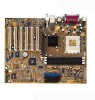
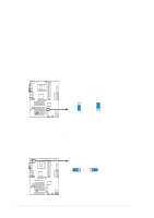
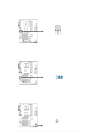
1.11 Jumpers This section describes and illustrates the jumpers on the motherboard. 1. USB device wake-up (3-pin USBPWR12,USBPWR34,USBPWR56) Set these jumpers to +5V to wake up the computer from S1 sleep mode (CPU stopped, DRAM refreshed, system running in low power mode) using the connected USB devices. Set to +5VSB to wake up from S3 sleep mode (no power to CPU, DRAM in slow refresh, power supply in reduced power mode). Both jumpers are set to pins 1-2 (+5V) by default because not all computers have the appropriate power supply to support this feature. The USBPWR12 and USBPWR34 jumpers are for the rear USB ports. USBPWR56 is for the internal USB header that you can connect to the front USB ports. This feature requires a power supply that can provide at least 1A on the +5VSB lead when these jumpers are set to +5VSB. Or, the system does not power up. The total current consumed must NOT exceed the power supply capability (+5VSB) whether under normal condition or in sleep mode. USBPW12 USBPW34 12 23 A7V8X-X ® +5V (Default) +5VSB USBPW56 12 23 A7V8X-X USB Device Wake Up +5V (Default) +5VSB 2. VCORE over-voltage (3-pin OVER_VOLT) When enabled, this jumper allows CPU VCORE ranges of 1.7V to 2.05V. When this jumper is disabled, VCORE setting has a range of +1.5V to +1.85V. You may adjust the CPU VCORE through the BIOS Setup. OVER_VOLT 12 23 Enable Disable (Default) A7V8X-X ® A7V8X-X OVER_VOLT Setting Setting to a very high core voltage may cause permanent damage to the CPU. It is recommended that you keep the default setting (Disable). ASUS A7V8X-X Motherboard 1-13
-
 1
1 -
2
-
3
-
4
-
5
-
6
-
7
-
8
-
9
-
10
-
11
-
12
-
13
-
14
-
15
-
16
-
17
-
 18
18 -
 19
19 -
 20
20 -
 21
21 -
 22
22 -
 23
23 -
 24
24 -
 25
25 -
 26
26 -
 27
27 -
 28
28 -
29
-
30
-
31
-
32
-
33
-
34
-
35
-
36
-
37
-
38
-
39
-
40
-
41
-
42
-
43
-
44
-
45
-
46
-
47
-
48
-
49
-
50
-
51
-
52
-
53
-
54
-
55
-
56
-
57
-
58
-
59
-
60
-
61
-
62
-
63
-
64
 |
 |
