Asus L1N64-SLI WS L1N64 WS Pro English user manual E3014 - Page 49
CPU, Chassis, Power, and Heat-pipe Fan connectors, pin CPU0_FAN, 4- pin CPU1-FAN, 3-pin HP_FAN1~3 3- - ws b cpu support
 |
UPC - 610839158225
View all Asus L1N64-SLI WS manuals
Add to My Manuals
Save this manual to your list of manuals |
Page 49 highlights
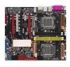
6. CPU, Chassis, Power, and Heat-pipe Fan connectors (4-pin CPU0_FAN, 4- pin CPU1-FAN, 3-pin HP_FAN1~3 3-pin CHA_ FAN1~4, SPS_FAN1) The fan connectors support cooling fans of 350 mA ~ 2000 mA (24 W max.) or a total of 1 A ~ 3.48 A (41.76 W max.) at +12V. Connect the fan cables to the fan connectors on the motherboard, making sure that the black wire of each cable matches the ground pin of the connector. Do not forget to connect the fan cables to the fan connectors. Insufficient air flow inside the system may damage the motherboard components. These are not jumpers! Do not place jumper caps on the fan connectors! L1N64-SLI WS CPU0_FAN SPS_FAN HP_FAN1 HP_FAN2 CPU1_FAN HP_FAN3 CHA_FAN1 CHA_FAN3 CHA_FAN2 CPU1_FAN HP_FAN1 HP_FAN2 SPS_FAN CPU0_FAN CPU1 FAN PWM CPU1 FAN IN CPU1 FAN PWR GND X +12V GND X +12V GND Rotation +12V GND CPU0 FAN PWM CPU0 FAN IN CPU0 FAN PWR GND HP_FAN3 GND +12V Rotation CHA_FAN1 CHA_FAN3 CHA_FAN2 CHA_FAN4 GND CHA_FANPWR Rotation GND +12V X GND CHA_FANPWR Rotation GND +12V X CHA_FAN4 L1N64-SLI WS Fan connectors ASUS L1N64-SLI WS 2-27
-
 1
1 -
2
-
3
-
4
-
5
-
6
-
7
-
8
-
9
-
10
-
11
-
12
-
13
-
14
-
15
-
16
-
17
-
18
-
19
-
20
-
21
-
22
-
23
-
24
-
25
-
26
-
27
-
28
-
29
-
30
-
31
-
32
-
33
-
34
-
35
-
36
-
37
-
38
-
39
-
40
-
41
-
42
-
43
-
 44
44 -
 45
45 -
 46
46 -
 47
47 -
 48
48 -
 49
49 -
 50
50 -
 51
51 -
 52
52 -
 53
53 -
 54
54 -
55
-
56
-
57
-
58
-
59
-
60
-
61
-
62
-
63
-
64
-
65
-
66
-
67
-
68
-
69
-
70
-
71
-
72
-
73
-
74
-
75
-
76
-
77
-
78
-
79
-
80
-
81
-
82
-
83
-
84
-
85
-
86
-
87
-
88
-
89
-
90
-
91
-
92
-
93
-
94
-
95
-
96
-
97
-
98
-
99
-
100
-
101
-
102
-
103
-
104
-
105
-
106
-
107
-
108
-
109
-
110
 |
 |
