Asus M4A77TD User Manual
Asus M4A77TD - Motherboard - ATX Manual
 |
UPC - 610839173099
View all Asus M4A77TD manuals
Add to My Manuals
Save this manual to your list of manuals |
Asus M4A77TD manual content summary:
- Asus M4A77TD | User Manual - Page 1
M4A77TD Motherboard - Asus M4A77TD | User Manual - Page 2
Product warranty or service will not be extended if: (1) the product is repaired, modified or altered, unless such repair, modification of alteration is authorized in writing by ASUS; or (2) the serial number of the product is defaced or missing. ASUS PROVIDES THIS MANUAL "AS IS" WITHOUT WARRANTY - Asus M4A77TD | User Manual - Page 3
About this guide viii M4A77TD specifications summary x Chapter 1: Product introduction 1.1 Welcome 1-1 1.2 Package contents 1-1 1.3 Special features 1-1 1.3.1 Product highlights 1-1 1.3.2 Innovative ASUS features 1-3 1.4 Before you proceed 1-5 1.5 Motherboard overview 1-6 1.5.1 Placement - Asus M4A77TD | User Manual - Page 4
Support DVD information 1-28 Chapter 2: BIOS information 2.1 Managing and updating your BIOS 2-1 2.1.1 ASUS Update utility 2-1 2.1.2 ASUS EZ Flash 2 utility 2-3 2.1.3 ASUS CrashFree BIOS utility 2-4 2.2 BIOS setup program 2-5 2.2.1 BIOS Configuration 2-10 2.4.2 CPU Configuration 2-13 2.4.3 - Asus M4A77TD | User Manual - Page 5
Mode 2-17 2.5.2 ACPI 2.0 Support 2-17 2.5.3 ACPI APIC Support 2-17 2.5.4 APM Configuration 2-17 2.5.5 HW Monitor Configuration 2-18 2.6 Boot menu 2-19 2.6.1 Boot Device Priority 2-19 2.6.2 Boot Settings Configuration 2-20 2.6.3 Security 2-21 2.7 Tools menu 2-22 2.7.1 ASUS EZ Flash 2 2-23 - Asus M4A77TD | User Manual - Page 6
cables for connection of the monitor to the graphics card is required to assure compliance with FCC regulations. radio noise emissions from digital apparatus set out in the Radio Interference Regulations at ASUS REACH website at http://green.asus.com/english/REACH.htm. DO NOT throw the motherboard in - Asus M4A77TD | User Manual - Page 7
supply is set to the service technician or your retailer. • The optical S/PDIF is an optional component (may or may not be included in your motherboard type. • RISK OF EXPLOSION IF BATTERY IS REPLACED BY AN INCORRECT TYPE. • DISPOSE OF USED BATTERIES ACCORDING TO THE ABOVE BATTERY-RELATED INSTRUCTIONS - Asus M4A77TD | User Manual - Page 8
the motherboard. How this guide is organized This guide contains the following parts: • Chapter 1: Product introduction This chapter describes the features of the motherboard and the new technology it supports. • Chapter 2: BIOS information This chapter tells how to change system settings through - Asus M4A77TD | User Manual - Page 9
guide To ensure that you perform certain tasks properly, take note of the following symbols used throughout this manual task. IMPORTANT: Instructions that you MUST updates. 1. ASUS websites The ASUS website provides updated information on ASUS hardware and software products. Refer to the ASUS - Asus M4A77TD | User Manual - Page 10
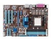
Memory Expansion slots Storage / RAID LAN Audio USB AMD® Socket AM3 for AMD® Phenom™ II / Athlon™ II / Sempron™ 100 series processors Supports 45nm CPU AMD® Cool 'n' Quiet™ 2.0 Technology (depends on CPU type) Supports CPU up to 140W * Refer to www.asus.com for the AMD® CPU support list AMD® 770 - Asus M4A77TD | User Manual - Page 11
BIOS ASUS special features ASUS overclocking features Accessories Support DVD Form factor 1 x PS/2 Keyboard / Mouse Combo port 1 x RJ-45 port 1 x COM port 1x LPT port 1 x Optical S/PDIF_OUT port 6 x USB 2.0/1.1 ports 8-channel audio ports 3 x USB 2.0/1.1 connectors support additional 6 USB - Asus M4A77TD | User Manual - Page 12
xii - Asus M4A77TD | User Manual - Page 13
II / Athlon™ II / Sempron™ 100 series CPU support This motherboard supports AMD® Socket AM3 multi-core processors with unique L3 cache and delivers better overclocking capabilities with less power consumption. It features dual-channel DDR3 1333 memory support and accelerates data transfer rate up to - Asus M4A77TD | User Manual - Page 14
AMD® 770 Chipset The AMD® 770 Chipset is designed to support up to 5200MT/s HyperTransport™ 3.0 (HT 3.0) interface speed and PCI Express 2.0 x16 graphics. It is optimized with AMD's latest AM3 multi-core CPUs to provide excellent system performance and overclocking capabilities. HyperTransport™ 3.0 - Asus M4A77TD | User Manual - Page 15
it on USB HDDs or flash drives, connect the drives to the motherboard USB port before turning on the computer. • The actual boot time depends on the system configuration. • ASUS Express Gate supports file uploading from SATA HDDs, ODDs and USB drives. It supports file downloading to USB drives only - Asus M4A77TD | User Manual - Page 16
restore a corrupted BIOS file using the bundled support DVD or a USB flash disk that contains the BIOS file. ASUS EZ Flash 2 ASUS EZ Flash 2 allows you to update the BIOS from a USB flash disk before entering the OS. ASUS Q-Fan ASUS Q-Fan technology intelligently adjusts the CPU fan speed according - Asus M4A77TD | User Manual - Page 17
following precautions before you install motherboard components or change any motherboard settings. • Unplug the power motherboard component. The illustration below shows the location of the onboard LED. M4A77TD SB_PWR ON OFF Standby Power Powered Off M4A77TD Onboard power LED ASUS M4A77TD - Asus M4A77TD | User Manual - Page 18
in the image below. 1.5.2 Screw holes Place six screws into the holes indicated by circles to secure the motherboard to the chassis. DO NOT overtighten the screws! Doing so can damage the motherboard. Place this side towards the rear of the chassis. M4A77TD 1-6 Chapter 1: Product introduction - Asus M4A77TD | User Manual - Page 19
-pin module) DDR3 DIMM_B1 (64bit, 240-pin module) SOCKET AM3 COM1 LPT CPU_FAN PRI_IDE USB34 LAN1_USB12 5 30.5cm(12.0in) AUDIO ICS 9LPRS485 AMD® 770 RTL 8112L PCIEX1_1 2 EATXPWR PCIEX1_2 PCIEX16 M4A77TD AMD® SB710 Lithium Cell CMOS Power Super I/O PCI1 PCI2 8Mb BIOS SATA1 SATA2 - Asus M4A77TD | User Manual - Page 20
into the socket to prevent bending the pins and damaging the CPU! 1.6.1 Installing the CPU To install a CPU: 1. Locate the CPU socket on the motherboard. M4A77TD M4A77TD CPU socket AM3 2. Press the lever sideways to unlock the Socket lever socket, then lift it up to a 90°-100° angle. Ensure - Asus M4A77TD | User Manual - Page 21
instructions. 7. Connect the CPU fan cable to the CPU_FAN connector on the motherboard. M4A77TD CPU_FAN GND CPU FAN PWR CPU FAN IN CPU FAN PWM M4A77TD CPU fan connector DO NOT forget to connect the CPU fan connector! Hardware monitoring errors can occur if you fail to plug this connector. ASUS - Asus M4A77TD | User Manual - Page 22
that you use only AMD-certified heatsink and fan assembly. To install the CPU heatsink and fan: 1. Place the heatsink on top of the installed CPU, ensuring that the heatsink fits properly on the retention module base. • The retention module base is already installed on the motherboard upon purchase - Asus M4A77TD | User Manual - Page 23
NOT forget to connect the CPU fan connector! Hardware monitoring errors can occur if you fail to plug this connector. 1.7 System memory 1.7.1 Overview This motherboard comes with four Double Data Rate 3 (DDR3) Dual Inline Memory Modules (DIMM) sockets. A DDR3 module has the same physical dimensions - Asus M4A77TD | User Manual - Page 24
�W�i�nd�o�w��s® OS if you want to install 4GB or more memory on the motherboard. • This motherboard does not support DIMMs made up of 256 megabits (Mb) chips or less. M4A77TD Motherboard Qualified Vendors Lists (QVL) DDR3-1866(O.C.)MHz capability Vendor Part No. Kingston KHX14900D3K3/3GX(XMP - Asus M4A77TD | User Manual - Page 25
27 8-8-8-24 DIMM support A* B* C* • • • • • • • • • • • • • • • • • • • • • • • • • • • • • • • • • • • • • • • • • We recommend that you install the DDR3 1600+ memory modules on the blue slots for better overclocking performance. DDR3-1333MHz capability - Asus M4A77TD | User Manual - Page 26
Kingston Micron Micron Micron F3-1066CL9T-6GBNQ DDR3-1333 CL9-9-9-24 GV34GB1333C7DC DDR3-1333 CL9-9-9-24 KVR1333D3N9/1G KVR1333D3N9/2G 24 9 7-7-7-24 9 9 9 N/A N/A 9 9 7-7-7-20 7-7-7-20 N/A N/A N/A N/A N/A N/A N/A N/A N/A N/A N/A 8-8-8-24 N/A N/A N/A N/A N/A 9 N/A 7-7-7-20 8-8-8-24 DIMM support - Asus M4A77TD | User Manual - Page 27
DDR3-1066MHz capability Vendor Part No. Size Elpida Elpida memory configuration. • C*: Supports two pairs of modules inserted into both the blue slots and the black slots as two pairs of dual-channel memory configuration. Visit the ASUS website at www.asus.com for the latest QVL. ASUS M4A77TD - Asus M4A77TD | User Manual - Page 28
so can cause severe damage to both the motherboard and the components. 1. Press the retaining clips outward to unlock a DIMM socket. 2. Align a DIMM DIMM: 1. Simultaneously press the retaining clips outward to unlock the DIMM. 2 Support the DIMM lightly with your fingers when pressing the - Asus M4A77TD | User Manual - Page 29
x1 slots This motherboard supports PCI Express x1 network cards, SCSI cards, and other cards that comply with the PCI Express specifications. 1.8.5 PCI Express x16 slot This motherboard supports a PCI Express x16 graphics card that comply with the PCI Express specifications. ASUS M4A77TD 1-17 - Asus M4A77TD | User Manual - Page 30
not need to clear the RTC when the system hangs due to overclocking. For system failure due to overclocking, use the CPU Parameter Recall (C.P.R) feature. Shut down and reboot the system so the BIOS can automatically reset parameter settings to default values. 1-18 Chapter 1: Product introduction - Asus M4A77TD | User Manual - Page 31
port connects to a microphone. 9. Side Speaker Out port (gray). This port connects to the side speakers in the 8-channel audio configuration. Refer to the audio configuration table on the next page for the function of the audio ports in the 2, 4, 6, or 8-channel configuration. ASUS M4A77TD 1-19 - Asus M4A77TD | User Manual - Page 32
may be different based on the OS). Go to Start > Control Panel > Sounds and Audio Devices > Sound Playback to configure the settings. 10. USB 2.0 ports 1 and 2. These two 4-pin Universal Serial Bus (USB) ports are for USB 2.0 devices. 11. USB 2.0 ports 3 and 4. These two 4-pin Universal Serial Bus - Asus M4A77TD | User Manual - Page 33
may not boot up if the power is inadequate. • If you are uncertain about the minimum power supply requirement for your system, refer to the Recommended Power Supply Wattage Calculator at http://support.asus. com/PowerSupplyCalculator/PSCalculator.aspx?SLanguage=en-us for details. ASUS M4A77TD 1-21 - Asus M4A77TD | User Manual - Page 34
motherboard's IDE connector, then select one of the following modes to configure your devices: Single device Two devices Drive jumper setting If any device jumper is set as "Cable-Select", ensure that all other device jumpers have the same setting. PRI_IDE PIN1 M4A77TD NOTE:Orient the red - Asus M4A77TD | User Manual - Page 35
on a hard disk drive that includes a RAID/AHCI set. • Due to Windows® XP limitation, Windows® XP may not recognize the USB floppy disk drive. • For more details on RAID/AHCI, refer to the RA ID/AHCI Supplementary Guide included in the folder named Manual in the support DVD. ASUS M4A77TD 1-23 - Asus M4A77TD | User Manual - Page 36
ATX power supply M4A77TD System panel connector • System power LED This 2-pin connector is for the system power LED. Connect the chassis power LED cable to this connector. The system power LED lights up when you turn on the system power, and blinks when the system is in sleep mode. • Hard disk drive - Asus M4A77TD | User Manual - Page 37
+ GND NC M4A77TD PIN 1 PIN 1 PIN 1 USB+5V USB_P7USB_P7+ GND USB+5V USB_P11USB_P11+ GND USB+5V USB_P9USB_P9+ GND M4A77TD USB2.0 connectors Never connect a 1394 cable to the USB connectors. Doing so will damage the motherboard! The USB 2.0 module is purchased separately. ASUS M4A77TD 1-25 - Asus M4A77TD | User Manual - Page 38
module to this connector to avail of the motherboard high-definition audio capability. • If you want to connect a high definition front panel audio module to this connector, set the Front Panel Select item in the BIOS to [HD Audio]. See section 2.4.4 Onboard Device Configuration for details. • The - Asus M4A77TD | User Manual - Page 39
connectors DO NOT forget to connect the fan cables to the fan connectors. Insufficient air flow inside the system may damage the motherboard components. These are not jumpers! DO NOT place jumper caps on the fan connectors. Only the 4-pin CPU fan supports the ASUS Q-Fan feature. ASUS M4A77TD 1-27 - Asus M4A77TD | User Manual - Page 40
to avail all motherboard features. The contents of the Support DVD are subject to change at any time without notice. Visit the ASUS website at www.asus.com for updates. To run the Support DVD Place the Support DVD into the optical drive. The DVD automatically displays the Drivers menu if Autorun - Asus M4A77TD | User Manual - Page 41
ASUS Update: 1. Place the support DVD into the optical drive. The Drivers menu appears. 2. Click the Utilities tab, then click ASUS Update. 3. Follow the onscreen instructions to complete the installation. Quit all Windows® applications before you update the BIOS using this utility. ASUS M4A77TD - Asus M4A77TD | User Manual - Page 42
Updating the BIOS To update the BIOS: 1. From the Windows® desktop, click Start > Programs > ASUS > ASUS Update > ASUS Update to launch the ASUS Update utility. 2. From the dropdown list, select either of the following methods: Updating from the Internet a. Select Update BIOS from the Internet, then - Asus M4A77TD | User Manual - Page 43
] Select or Load [Tab] Switch [Up/Down/Home/End] Move [B] Backup [V] Drive Info [ESC] Exit • This function supports USB flash disks with FAT 32/16 format and single partition only. • DO NOT shut down or reset the system while updating the BIOS to prevent system boot failure! ASUS M4A77TD 2-3 - Asus M4A77TD | User Manual - Page 44
into M4A77TD.ROM. • The BIOS file in the support DVD may not be the latest version. Download the latest BIOS file from the ASUS website at www.asus.com. • The removable devices that ASUS CrashFree BIOS supports vary with motherboard models. For motherboards without a floppy connector, prepare a USB - Asus M4A77TD | User Manual - Page 45
Defaults item under the Exit menu. See section 2.8 Exit Menu. • The BIOS setup screens in this chapter are for reference only. They may not exactly match what you see on your screen. • Visit the ASUS website at www.asus.com to download the latest BIOS file for this motherboard. ASUS M4A77TD 2-5 - Asus M4A77TD | User Manual - Page 46
menu screen Menu items Menu bar Configuration fields Main Advanced Power BIOS SETUP UTILITY Boot Tools Exit Main Settings System Time [19:34:30] System Date [Fri 07/31/2009] Primary IDE Master Primary IDE Slave SATA1 SATA2 SATA3 SATA4 SATA5 SATA6 SATA Configuration :[ - Asus M4A77TD | User Manual - Page 47
: 0x1 GART Error Reporting Microcode Updation Secure Virtual Machine Mode Cool 'n' Quiet ACPI SRAT Table C1E Configuration Advanced Clock Calibration [Disabled] [Enabled] [Disabled] [Enalbed] [Enabled] [Disabled] [Disabled] Sets the ratio between CPU Core Clock and the FSB Frequency. NOTE - Asus M4A77TD | User Manual - Page 48
items and how to navigate through them. Main Advanced Main Settings Power BIOS SETUP UTILITY Boot Tools Exit System Time [19:34:30] System Date [ is installed in the system. Type [Auto] Selects the type of IDE/SATA drive. Setting this item to [Auto] allows automatic selection of the - Asus M4A77TD | User Manual - Page 49
the device supports multisector transfer feature. When this item is set to [ driver, so that you can use SATA 1/2/3/4/5/6 in AHCI mode under OS. • When SATA 1/2/3/4 are configured as [AHCI] and SATA 5/6 are configured as [IDE], you can access the devices on SATA 5/6 before entering OS. ASUS M4A77TD - Asus M4A77TD | User Manual - Page 50
items and configuration options in this menu may vary depending on the AMD CPU type. Ai Overclock Tuner [Auto] Selects the CPU overclocking options to achieve desired CPU internal frequency. Configuration options: [Auto] [Manual] [Overclock Profile] [Test Mode] 2-10 Chapter 2: BIOS information - Asus M4A77TD | User Manual - Page 51
appears when you set Ai Overclock Tuner to [Overclock Profile]. Overclock Options [Auto] Selects the overclocking profile. Configuration options: [Auto] [Overclock 2%] [Overclock 5%] [Overclock 8%] [Overclock 10%] CPU Ratio [Auto] Sets the ratio between the CPU Core Clock and the CPU Bus Frequency - Asus M4A77TD | User Manual - Page 52
[1067MHz] [1333MHz] [1600MHz] Memory Over Voltage [Auto] Sets the memory over voltage. The values range from 1.5000V to 2.2050V with a 0.0150V increment. Use the / keys to adjust the value. Configuration options: [Auto] [Max. = 2.2050V] [Min. = 1.5000V] DRAM Timing/Driving Configuration The - Asus M4A77TD | User Manual - Page 53
show the CPU-related information that the BIOS automatically detects. GART Error Reporting [Disabled] This option should remain disabled for the normal operation. The driver developer may enable it for testing purpose. Configuration options: [Disabled] [Enabled] Microcode Updation [Enabled] Enables - Asus M4A77TD | User Manual - Page 54
, the CPU core frequency and voltage will be reduced during the system halt state to decrease power consumption. Configuration options: [Disabled] [Enabled] Advanced Clock Calibration [Disabled] Adjusts the processor's overclocking capability. When this item is set to [Auto], the BIOS automatically - Asus M4A77TD | User Manual - Page 55
No] When this item is set to [No], BIOS configures all the devices in the system. When this item is set to [Yes] and if you install a Plug and Play operating system, the operating system configures the Plug and Play devices not required for boot. Configuration options: [No] [Yes] ASUS M4A77TD 2-15 - Asus M4A77TD | User Manual - Page 56
2.0 Controller [Enabled] Enables or disables USB 2.0 Controllers. Configuration options: [Disabled] [Enabled] Legacy USB Support [Auto] Allows you to enable or disable support for Legacy USB storage devices, including USB flash drives and USB hard drives. Setting to Auto allows the system to detect - Asus M4A77TD | User Manual - Page 57
BIOS SETUP UTILITY Boot Tools Exit Power Settings Suspend Mode [Auto] ACPI 2.0 Support [Enabled] ACPI APIC Support support in the Advanced Programmable Interrupt Controller (APIC). When set to Enabled, the ACPI APIC table pointer is included in the RSDT pointer list Enabled] ASUS M4A77TD 2-17 - Asus M4A77TD | User Manual - Page 58
motherboard and CPU temperatures. Select Ignored if you do not wish to display the detected temperatures. CPU the ASUS Q-Fan feature that smartly adjusts the CPU fan speeds Sets the smart Q-Fan start working temperature. Configuration options: [25ºC] ~ [48ºC] Fan Auto Mode Full Speed Temp [55ºC] Sets - Asus M4A77TD | User Manual - Page 59
options: [Removable Dev.] [Hard Drive] [ATAPI CD-ROM] [Disabled] • To select the boot device during system startup, press when ASUS logo appears. • To access Windows OS in Safe Mode, do any of the following: • Press when ASUS logo appears. • Press after POST. ASUS M4A77TD 2-19 - Asus M4A77TD | User Manual - Page 60
(POST) while booting to decrease the time needed to boot the system. When this item is set to [Disabled], BIOS performs all the Set this item to [Enabled] to use the ASUS MyLogo2™ feature. AddOn ROM Display Mode [Force BIOS] Sets the display mode for option ROM. Configuration options: [Force BIOS - Asus M4A77TD | User Manual - Page 61
If you forget your BIOS password, you can clear it by erasing the CMOS Real Time Clock (RTC) RAM. See section 1.9 Jumpers for information on how to erase the RTC RAM. After you have set a supervisor password, the allows viewing and changing all the fields in the Setup utility. ASUS M4A77TD 2-21 - Asus M4A77TD | User Manual - Page 62
Not Installed. After you set a password, this item shows Installed. To set a User Password: 1. BIOS SETUP UTILITY Boot Tools Exit ASUS EZ Flash 2 Express Gate Enter OS Timer Reset User Data [Auto] [10 Seconds] [No] Press ENTER to run the utility to select and update BIOS. This utility supports - Asus M4A77TD | User Manual - Page 63
Reset] When setting this item to [Reset], ensure to save the setting to the BIOS so that settings. 2.7.3 AI NET 2 Check Realtek LAN cable [Disabled] Enables or disables checking of the Realtek LAN cable during the Power-On Self‑Test (POST). Configuration options: [Disabled] [Enabled] ASUS M4A77TD - Asus M4A77TD | User Manual - Page 64
values for the BIOS items, and save or discard your changes to the BIOS items. Main Advanced BIOS SETUP UTILITY Power Boot Tools Exit Exit ensure the values you selected are saved to the CMOS RAM. An onboard backup battery sustains the CMOS RAM so it stays on even when the PC is turned
-
 1
1 -
 2
2 -
 3
3 -
 4
4 -
 5
5 -
 6
6 -
 7
7 -
8
-
9
-
10
-
11
-
12
-
13
-
14
-
15
-
16
-
17
-
18
-
19
-
20
-
21
-
22
-
23
-
24
-
25
-
26
-
27
-
28
-
29
-
30
-
31
-
32
-
33
-
34
-
35
-
36
-
37
-
38
-
39
-
40
-
41
-
42
-
43
-
44
-
45
-
46
-
47
-
48
-
49
-
50
-
51
-
52
-
53
-
54
-
55
-
56
-
57
-
58
-
59
-
60
-
61
-
62
-
63
-
64
 |
 |

Motherboard
M4A77TD