Asus MAXIMUS IV EXTREME-Z User Manual - Page 52
Onboard LEDs, 3 Extreme Tweaker menu, CPU LED, Memory LED, PCH LED - no display
 |
View all Asus MAXIMUS IV EXTREME-Z manuals
Add to My Manuals
Save this manual to your list of manuals |
Page 52 highlights
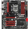
2.2.7 Onboard LEDs The motherboard comes with a set of LEDs that indicate the voltage conditions of CPU, memory, northbridge and southbridge. You may adjust the voltages in BIOS. There are also an LED for hard disk drive activity and an onboard switch for power status. For more information about voltage adjustment, refer to 3.3 Extreme Tweaker menu. 1. CPU LED The CPU LED has four voltage displays: CPU Voltage, VCCSA, VCCIO, and CPU PLL Voltage; you can select the voltage to display in BIOS. Refer to the illustration below for the location of the CPU LED and the table below for LED definition. 2. Memory LED The Memory LED has one voltage display: DRAM Voltage. Refer to the illustration below for the location of the memory LED and the table below for LED definition. 3. PCH LED PCH LED has two different voltage displays: PCH Voltage and PCH PLL Voltage. Refer to the illustration below for the location of the PCH LED and the table below for LED definition. Normal (blue) CPU Voltage (default) 0.8-1.4 VCCSA Voltage 0.8-1.1 VCCIO Voltage 0.8-1.15 CPU PLL Voltage 1.2-2.0 High (yellow) 1.40500-1.55 1.10625-1.2 1.15625�-�1�.2�5� 2.00625-2.1 Crazy (red) 1.55500-by CPU 1.20625-by CPU 1.25625-by CPU 2.10625-by CPU 2-20 Chapter 2: Hardware information
-
 1
1 -
2
-
3
-
4
-
5
-
6
-
7
-
8
-
9
-
10
-
11
-
12
-
13
-
14
-
15
-
16
-
17
-
18
-
19
-
20
-
21
-
22
-
23
-
24
-
25
-
26
-
27
-
28
-
29
-
30
-
31
-
32
-
33
-
34
-
35
-
36
-
37
-
38
-
39
-
40
-
41
-
42
-
43
-
44
-
45
-
46
-
 47
47 -
 48
48 -
 49
49 -
 50
50 -
 51
51 -
 52
52 -
 53
53 -
 54
54 -
 55
55 -
 56
56 -
 57
57 -
58
-
59
-
60
-
61
-
62
-
63
-
64
-
65
-
66
-
67
-
68
-
69
-
70
-
71
-
72
-
73
-
74
-
75
-
76
-
77
-
78
-
79
-
80
-
81
-
82
-
83
-
84
-
85
-
86
-
87
-
88
-
89
-
90
-
91
-
92
-
93
-
94
-
95
-
96
-
97
-
98
-
99
-
100
-
101
-
102
-
103
-
104
-
105
-
106
-
107
-
108
-
109
-
110
-
111
-
112
-
113
-
114
-
115
-
116
-
117
-
118
-
119
-
120
-
121
-
122
-
123
-
124
-
125
-
126
-
127
-
128
-
129
-
130
-
131
-
132
-
133
-
134
-
135
-
136
-
137
-
138
-
139
-
140
-
141
-
142
-
143
-
144
-
145
-
146
-
147
-
148
-
149
-
150
-
151
-
152
-
153
-
154
-
155
-
156
-
157
-
158
-
159
-
160
-
161
-
162
-
163
-
164
-
165
-
166
-
167
-
168
-
169
-
170
-
171
-
172
-
173
-
174
-
175
-
176
-
177
-
178
-
179
-
180
-
181
-
182
-
183
-
184
-
185
-
186
-
187
-
188
-
189
-
190
-
191
-
192
-
193
-
194
-
195
-
196
 |
 |
