Asus NCCH-DR NCCH-DR User Manual English Version - Page 52
opening at the back of the system chassis.
 |
View all Asus NCCH-DR manuals
Add to My Manuals
Save this manual to your list of manuals |
Page 52 highlights
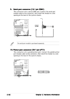
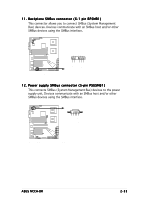
9 . Serial port connector (10-1 pin COM2) This connector is for a serial (COM) port. Connect the serial port module cable to this connector, then install the module to a slot opening at the back of the system chassis. COM2 PIN 1 NCCH-DR NCCH-DR Serial port2 (COM2) connector The serial port module is purchased separately. 10. Printer port connector (26-1 pin LPT1) This connector is for a parallel printer port. Connect the parallel printer port module cable to this connector, then install the module to a slot opening at the back of the system chassis. LPT1 Pin 1 NCCH-DR NCCH-DR Parallel port connector AFD# ERROR# PINIT# SLIN# GND GND GND GND GND GND GND GND STB# SPD0 SPD1 SPD2 SPD3 SPD4 SPD5 SPD6 SPD7 ACK# BUSY PE SLCT 2-32 Chapter 2: Hardware information
-
 1
1 -
2
-
3
-
4
-
5
-
6
-
7
-
8
-
9
-
10
-
11
-
12
-
13
-
14
-
15
-
16
-
17
-
18
-
19
-
20
-
21
-
22
-
23
-
24
-
25
-
26
-
27
-
28
-
29
-
30
-
31
-
32
-
33
-
34
-
35
-
36
-
37
-
38
-
39
-
40
-
41
-
42
-
43
-
44
-
45
-
46
-
 47
47 -
 48
48 -
 49
49 -
 50
50 -
 51
51 -
 52
52 -
 53
53 -
 54
54 -
 55
55 -
 56
56 -
 57
57 -
58
-
59
-
60
-
61
-
62
-
63
-
64
-
65
-
66
-
67
-
68
-
69
-
70
-
71
-
72
-
73
-
74
-
75
-
76
-
77
-
78
-
79
-
80
-
81
-
82
-
83
-
84
-
85
-
86
-
87
-
88
-
89
-
90
-
91
-
92
-
93
-
94
-
95
-
96
-
97
-
98
-
99
-
100
-
101
-
102
-
103
-
104
-
105
-
106
-
107
-
108
-
109
-
110
 |
 |
