Asus P2B P2B User Manual - Page 31
SB-Link™ Connector 6-1 pin SBLINK - isa
 |
View all Asus P2B manuals
Add to My Manuals
Save this manual to your list of manuals |
Page 31 highlights
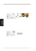
III. HARDWARE SETUP 13. Wake-on-LAN Connector (3-pin WOL_CON) The WOL_CON connector powers up the system when a wakeup packet or signal is received from the network through the ASUS PCI-L101 LAN card (see section VII. ASUS LAN Card). IMPORTANT: This feature requires that the WAKE On LAN Power Up Control is set to Enabled (see "Power Management Setup" under IV. BIOS SOFTWARE) and that your system has an ATX power supply with at least 720mA +5V standby power. +5VSB (No Connection) Ground R III. H/W SETUP Connectors P2B Wake on LAN Connector 14. SB-Link™ Connector (6-1 pin SBLINK) Using Intel's PC-PCI DMA and serialized IRQ protocols found in this motherboard's AGPset, this connector allows Sound Blaster 16 compatibility to AWE64D (Digital) or other PCI audio cards, enabling users to play Real-mode DOS games and multimedia applications. SB-Link acts as a bridge between the motherboard and the PCI audio card by providing the DMA and IRQ signals present in the ISA bus but not available on the PCI bus. PC/PCI Grant 1 Sideband Signal DGND 5 2 DGND 4 PC/PCI Request Sideband Signal 6 Serial IRQ NOTE: Pin 3 is removed to ensure the correct orientation of the cable on it. R P2B SB-Link™ Connector 15. SMBus Connector (5-1 pin SMB) This connector allows you to connect SMBus devices. SMBus devices communicate by means of the SMBus with an SMBus host and/or other SMBus devices. The SMBus or System Management Bus is a specific implementation of an I2C bus, which is a multi-master bus, that is, multiple chips can be connected to the same bus and each one can act as a master by initiating data transfer. 1 SMBCLK Ground SMBDATA +5V R P2B SMBus Connector ASUS P2B User's Manual 31
-
 1
1 -
2
-
3
-
4
-
5
-
6
-
7
-
8
-
9
-
10
-
11
-
12
-
13
-
14
-
15
-
16
-
17
-
18
-
19
-
20
-
21
-
22
-
23
-
24
-
25
-
 26
26 -
 27
27 -
 28
28 -
 29
29 -
 30
30 -
 31
31 -
 32
32 -
 33
33 -
 34
34 -
 35
35 -
 36
36 -
37
-
38
-
39
-
40
-
41
-
42
-
43
-
44
-
45
-
46
-
47
-
48
-
49
-
50
-
51
-
52
-
53
-
54
-
55
-
56
-
57
-
58
-
59
-
60
-
61
-
62
-
63
-
64
-
65
-
66
-
67
-
68
 |
 |
