Asus P4PE-X P4PE-X User Manual
Asus P4PE-X Manual
 |
View all Asus P4PE-X manuals
Add to My Manuals
Save this manual to your list of manuals |
Asus P4PE-X manual content summary:
- Asus P4PE-X | P4PE-X User Manual - Page 1
Motherboard P4PE-X User Guide - Asus P4PE-X | P4PE-X User Manual - Page 2
Product warranty or service will not be extended if: (1) the product is repaired, modified or altered, unless such repair, modification of alteration is authorized in writing by ASUS; or (2) the serial number of the product is defaced or missing. ASUS PROVIDES THIS MANUAL "AS IS" WITHOUT WARRANTY - Asus P4PE-X | P4PE-X User Manual - Page 3
v Safety information vi About this guide vii ASUS contact information viii P4PE-X specifications summary ix Chapter 1: Product introduction 1.1 Welcome 1-2 1.2 Package contents 1-2 1.3 Special features 1-3 1.4 Motherboard components 1-4 1.5 Motherboard layout 1-7 1.6 Before you proceed - Asus P4PE-X | P4PE-X User Manual - Page 4
23 2.5.1 Power Up Control 2-25 2.5.2 Hardware Monitor 2-27 2.6 Boot Menu 2-28 2.7 Exit Menu 2-30 Chapter 3: Software support 3.1 Install an operating system 3-2 3.2 Support CD information 3-2 3.2.1 Running the support CD 3-2 3.2.2 Drivers menu 3-3 3.2.3 Utilities menu 3-4 3.2.4 ASUS Contact - Asus P4PE-X | P4PE-X User Manual - Page 5
tested and found to comply with the limits for a Class B digital device, pursuant to Part 15 of the FCC Rules. These limits are designed energy and, if not installed and used in accordance with manufacturer's instructions, may cause harmful interference to radio communications. However, there is no - Asus P4PE-X | P4PE-X User Manual - Page 6
your local power company. • If the power supply is broken, do not try to fix it by yourself. Contact a qualified service technician or your retailer. Operation safety • Before installing the motherboard and adding devices on it, carefully read all the manuals that came with the package. • Before - Asus P4PE-X | P4PE-X User Manual - Page 7
product and software updates. 1. ASUS Websites The ASUS websites worldwide provide updated information on ASUS hardware and software products. The ASUS websites are listed in the ASUS Contact Information on page viii. 2. Optional Documentation Your product package may include optional documentation - Asus P4PE-X | P4PE-X User Manual - Page 8
contact information ASUSTeK COMPUTER INC. (Asia-Pacific) Address: 150 Li-Te Road, Peitou, Taipei, Taiwan 112 General Tel: +886-2-2894-3447 General Fax: +886-2-2894-3449 General Email: [email protected] Technical Support MB/Others (Tel): +886-2-2890-7121 (English) Notebook (Tel): +886 - Asus P4PE-X | P4PE-X User Manual - Page 9
CPU Chipset Front Side Bus (FSB) Memory Expansion slots IDE Audio (optional) LAN (optional) Special features Rear panel I/O Internal I/O Socket 478 for Intel® Pentium® 4 On-die 512KB/256KB L2 cache with full speed Intel® Hyper-Threading technology ready New power design for up to 3.06 GHz or faster - Asus P4PE-X | P4PE-X User Manual - Page 10
Form Factor Support CD contents 2Mb Flash ROM, Award BIOS, TCAV, PnP, DMI2.0, SM BIOS2.3, CrashFree BIOS, ASUS EZ Flash PCI 2.2, USB 2.0 WfM 2.0. DMI 2.0, WOL/WOR by PME, chassis intrusion, SMBus ATX form factor: 12 in x 9.0 in (30.5 cm x 22.9 cm) Device drivers ASUS PC Probe ASUS LiveUpdate Trend - Asus P4PE-X | P4PE-X User Manual - Page 11
Chapter 1 This chapter describes the features of the P4PE-X motherboard. It includes brief descriptions of the motherboard components, and illustrations of the layout, jumper settings, and connectors. Product introduction - Asus P4PE-X | P4PE-X User Manual - Page 12
installing the motherboard, and hardware devices on it, check the items in your package with the list below. 1.2 Package contents Check your P4PE-X package for the following items. ASUS P4PE-X motherboard ATX form factor: 12 in x 9 in (30.5 cm x 22.9 cm) ASUS P4PE-X series support CD 80-conductor - Asus P4PE-X | P4PE-X User Manual - Page 13
a 478-pin surface mount ZIF socket. See page 1-10 for more information. DDR memory support Employing the Double Data Rate (DDR) memory technology, the P4PE-X motherboard supports up to 2GB of system memory using unbuffered non-ECC PC3200/2700/2100/1600 DDR DIMMs. Memory support depends on the CPU - Asus P4PE-X | P4PE-X User Manual - Page 14
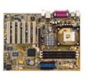
components Before you install the motherboard, learn about its major components and available features to facilitate the installation and future upgrades. Refer to the succeeding pages for the component descriptions. 1 23 4 5 6 7 - Asus P4PE-X | P4PE-X User Manual - Page 15
from the ATX 12V power supply. 2 CPU socket. A 478-pin surface mount, Zero Insertion Force (ZIF) socket for the Intel® Pentium® 4 Processor, with 800/533/400 MHz system bus that allows 6.4GB/s, 4.3GB/s, and 3.2GB/s data transfer rates, respectively. 3 North bridge controller. The Intel® 845PE Memory - Asus P4PE-X | P4PE-X User Manual - Page 16
an AC'97 CODEC that allows 6-channel audio playback. The audio CODEC provides six DAC channels for 5.1 surround sound, S/PDIF output, AUX and Line In stereo inputs, integrated headphone amplifier, greater than 90dB dynamic range, and stereo Mic PREAMP support. 15 LAN controller. The BroadCom BCM4401 - Asus P4PE-X | P4PE-X User Manual - Page 17
Gbit/Fast BCM5702/4401 Ethernet Audio Codec SPDIF1 CD1 AUX1 ATX12V1 Intel 845PE Memory Controller Hub (MCH) Accelerated Graphics Port (AGP) PCI1 P4PE-X PCI2 PCI3 PCI4 PCI5 PCI6 01 23 45 Intel I/O Controller Hub (ICH4) ® CR2032 3V Lithium Cell CMOS Power CLRTC ASUS ASIC with Hardware - Asus P4PE-X | P4PE-X User Manual - Page 18
before you install motherboard components or change any motherboard settings. 1. Unplug the power cord from the wall socket before touching any ATX power supply is switched off or the power cord is detached from the power supply. Failure to do so may cause severe damage to the motherboard, - Asus P4PE-X | P4PE-X User Manual - Page 19
in the image below. 1.7.2 Screw holes Place seven (7) screws into the holes indicated by circles to secure the motherboard to the chassis. Do not overtighten the screws! Doing so may damage the motherboard. Place this side towards the rear of the chassis ASUS P4PE-X motherboard user guide 1-9 - Asus P4PE-X | P4PE-X User Manual - Page 20
Central Processing Unit (CPU) 1.8.1 Overview The motherboard comes with a surface mount 478-pin Zero Insertion Force (ZIF) socket. The socket is designed for the Intel® Pentium® 4 Processor in the 478-pin package with 512KB L2 cache on 0.13 micron process. This processor supports 800*/533/400MHz - Asus P4PE-X | P4PE-X User Manual - Page 21
the socket lever to secure the CPU. The lever clicks on the side tab to indicate that it is locked. 6. Install a CPU heatsink and fan following the instructions that came with the heatsink package. 7. Connect the CPU fan cable to the CPU_FAN1 connector on the motherboard. ASUS P4PE-X motherboard - Asus P4PE-X | P4PE-X User Manual - Page 22
) sockets. These sockets support up to 2GB system memory using 184-pin unbuffered non-ECC PC3200/2700/2100/1600 DDR DIMMs. The following figure illustrates the location of the DDR DIMM sockets. If you wish to use a PC3200 (400MHz) DDR module, you need to install a CPU with 800MHz FSB. ® P4PE-X 80 - Asus P4PE-X | P4PE-X User Manual - Page 23
DIMM notch 2. Align a DIMM on the socket such that the notch on the DIMM matches the break on the socket. 3. Firmly insert the DIMM into the socket until the retaining clips snap back in place and the DIMM is properly seated. Unlocked Retaining Clip ASUS P4PE-X motherboard user guide 1-13 - Asus P4PE-X | P4PE-X User Manual - Page 24
following the instructions that came with the chassis. NOTE: The AGP slot supports only 1.5V AGP cards. 2. Turn on the system and change the necessary BIOS settings, if any. See Chapter 2 for BIOS information. 3. Assign an IRQ to the card. Refer to the tables below. 4. Install the drivers and/or - Asus P4PE-X | P4PE-X User Manual - Page 25
not need to clear the RTC when the system hangs due to overclocking. For system failure due to overclocking, use the C.P.R. (CPU Parameter Recall) feature. Shut down and reboot the system so BIOS can automatically reset parameter settings to default values. ASUS P4PE-X motherboard user guide 1-15 - Asus P4PE-X | P4PE-X User Manual - Page 26
motherboard. 1. Hard disk activity LED (2-pin IDE_LED1) This connector supplies power to the hard disk activity LED. The read or write activities of any device the pins. CHASSIS1 +5VSB_MB Chassis Signal GND ® P4PE-X P4PE-X Chassis Alarm Lead (Default) 1-16 Chapter 1: Product introduction - Asus P4PE-X | P4PE-X User Manual - Page 27
the other end to the floppy drive. (Pin 5 is removed to prevent incorrect insertion when using ribbon cables with pin 5 plug). FLOPPY1 ® P4PE-X NOTE: Orient the red markings on the floppy ribbon cable to PIN 1. PIN 1 P4PE-X Floppy Disk Drive Connector ASUS P4PE-X motherboard user guide 1-17 - Asus P4PE-X | P4PE-X User Manual - Page 28
3VDC +12V DC GND P4PE-X ATX & Auxiliary Power Connectors 6. Digital audio connector (4-1 pin SPDIF1) This connector is for the S/PDIF audio module that allows digital instead of analog sound output. Connect one end of the audio cable to the S/PDIF Out connector on the motherboard, and the other - Asus P4PE-X | P4PE-X User Manual - Page 29
(4-pin CD1, AUX1) These connectors allow you to receive stereo audio input from sound sources such as a CD-ROM, TV tuner, or MPEG card. ® P4PE-X CD1(Black) AUX1 (White) Left Audio Channel Ground Ground Right Audio Channel P4PE-X Internal Audio Connectors ASUS P4PE-X motherboard user guide 1-19 - Asus P4PE-X | P4PE-X User Manual - Page 30
the front panel audio cable. ® P4PE-X FP_AUDIO1 P4PE-X Front Panel Audio Connector 10. USB header (10-1 pin USB_56) If the USB ports on the rear panel are inadequate, a USB header is available for additional USB ports. The USB header complies with USB 2.0 specification that supports up to 480 - Asus P4PE-X | P4PE-X User Manual - Page 31
. Keyboard Lock Speaker Power LED Connector +5 V PLED Keylock Ground +5V Ground Ground Speaker ExtSMI# Ground PWRBIN Ground Reset Ground ® P4PE-X Reset SW SMI Lead ATX Power Switch* * Requires an ATX power supply. P4PE-X System Panel Connectors ASUS P4PE-X motherboard user guide 1-21 - Asus P4PE-X | P4PE-X User Manual - Page 32
connector allows you to manually place the system into a suspend mode, or "green" mode, where system activity is instantly decreased to save power and to expand the life of certain system components. Attach the casemounted suspend switch to this 2-pin connector. • ATX Power Switch / Soft-Off Switch - Asus P4PE-X | P4PE-X User Manual - Page 33
Chapter 2 This chapter tells how to change system settings through the BIOS Setup menus. Detailed descriptions of the BIOS parameters are also provided. BIOS information - Asus P4PE-X | P4PE-X User Manual - Page 34
firmware so it is accessible by simply pressing + during the Power-On Self Tests (POST). Follow these steps to update the BIOS using ASUS EZ Flash. 1. Download the latest BIOS file from the ASUS website (see ASUS contact information on page viii). Save the file to a floppy disk. Write - Asus P4PE-X | P4PE-X User Manual - Page 35
main BIOS area. DO NOT shutdown or reset the system while updating the BIOS area! Doing so may cause system boot failure. 8. When the update process is done, the message, "Press a key to reboot" appears. Press any key to reboot the system with the new BIOS. ASUS P4PE-X motherboard user guide 2-3 - Asus P4PE-X | P4PE-X User Manual - Page 36
Using AFLASH to update the BIOS Creating a bootable disk AFLASH.EXE is a Flash Memory Writer utility that updates the BIOS by uploading a new BIOS file to the programmable flash ROM on the motherboard. This file works only in DOS mode. To determine the BIOS version of your motherboard, check the - Asus P4PE-X | P4PE-X User Manual - Page 37
.XXX, then press . Updating the BIOS Update the BIOS only if you have problems with the motherboard and you are sure that the new BIOS revision will solve your problems. Careless updating may result to more problems with the motherboard! 1. Download an updated ASUS BIOS file from the Internet - Asus P4PE-X | P4PE-X User Manual - Page 38
, and if the problem persists, load the original BIOS file you saved to the boot disk. If the Flash Memory Writer utility is not able to successfully update a complete BIOS file, the system may not boot. If this happens, call the ASUS service center for support. 2-6 Chapter 2: BIOS information - Asus P4PE-X | P4PE-X User Manual - Page 39
BIOS update procedure in section "2.1.2 Using AFLASH to update the BIOS." 2.1.4 BIOS beep codes When you turn the power on and the system runs POST (Power On Self Tests), you will hear BIOS card memory bad CPU overheated; System running at a lower frequency ASUS P4PE-X motherboard user guide 2-7 - Asus P4PE-X | P4PE-X User Manual - Page 40
Setup program This motherboard supports a programmable Flash ROM that you can update using the provided utility described in section "2.1 Managing and updating your BIOS." Use the BIOS Setup program when you are installing a motherboard, reconfiguring your system, or prompted to "Run Setup". This - Asus P4PE-X | P4PE-X User Manual - Page 41
anywhere in the BIOS Setup Jumps to window. Use and or the up and down arrow keys to scroll through the entire help document. Press to display the first page, press to go to the last page. To exit the help window, press or . ASUS P4PE-X motherboard user guide - Asus P4PE-X | P4PE-X User Manual - Page 42
Setup program, note that explanations appear in the Item Specific Help window located to the right of each menu. This window displays the help text for the currently highlighted field. 2.3 Main Shift> + keys to move between the month, day, and year fields. 2-10 Chapter 2: BIOS information - Asus P4PE-X | P4PE-X User Manual - Page 43
2 seconds, then power up the system. Refer to section "2.1 Managing and updating your BIOS" on how to update the BIOS. Halt On [All Memory [XXX MB] This field automatically displays the amount of conventional memory detected by the system during the boot process. ASUS P4PE-X motherboard user guide - Asus P4PE-X | P4PE-X User Manual - Page 44
, Setup may detect incorrect parameters. In these cases, select [User Type HDD] to manually enter the IDE hard disk drive parameters. Refer to the next section for to fail to recognize the installed hard disk. [User Type HDD] Manually enter the number of cylinders, heads and sectors per track for - Asus P4PE-X | P4PE-X User Manual - Page 45
disk drives [Other ATAPI Device] - for IDE devices not listed here After making HDD] and the Translation Method field to [Manual]. CHS Capacity This field shows the drive's maximum CHS capacity as calculated by the BIOS based on the drive information you entered. ASUS P4PE-X motherboard user guide - Asus P4PE-X | P4PE-X User Manual - Page 46
supports. Note that when this field is automatically configured, the set value may not always be the fastest value for the drive. You may also manually manually. To make changes to this field, set the Type field to [User Type HDD and data integrity for compatible IDE devices. Set to [Disabled] to - Asus P4PE-X | P4PE-X User Manual - Page 47
field in conjunction with CPU Frequency (MHz) to match the speed of the CPU. The item CPU Frequency Multiple is accessible only if you have an unlocked processor. If your processor frequency multiple is locked, you cannot change the setting of this item. ASUS P4PE-X motherboard user guide 2-15 - Asus P4PE-X | P4PE-X User Manual - Page 48
[Enabled] This item allows you to enable or disable the processor Hyper-Threading Technology. Configuration options: [Disabled] [Enabled] The item Hyper-Threading Technology appears only if you installed an Intel Pentium 4 CPU that supports this feature. 2-16 Chapter 2: BIOS information - Asus P4PE-X | P4PE-X User Manual - Page 49
[Auto] OS/2 Onboard Memory > 64M [Disabled] When using OS/2 operating systems with installed DRAM of greater than 64MB, you need to set this option to [Enabled]. Otherwise, leave to the default setting [Disabled]. Configuration options: [Disabled] [Enabled] ASUS P4PE-X motherboard user guide 2-17 - Asus P4PE-X | P4PE-X User Manual - Page 50
reading the contents in the SPD (Serial Presence Detect) device. The EEPROM on the memory module stores critical information about the module, such as memory type, size, speed, voltage interface, and module banks . Configuration options: [8T] [7T] [6T] [5T] 2-18 Chapter 2: BIOS information - Asus P4PE-X | P4PE-X User Manual - Page 51
performance when set to Turbo mode. If you encounter any problems with the Turbo setting, set to Optimal or Auto. memory space unavailable to other system components. Expansion cards can only access memory up to 16MB. Configuration options: [Disabled] [Enabled] ASUS P4PE-X motherboard user guide - Asus P4PE-X | P4PE-X User Manual - Page 52
Enabled], this feature frees the PCI bus when the CPU is accessing 8-bit ISA cards. This process normally consumes the USB 2.0 high-speed drive strength reference voltage. Configuration options: [Low] [Medium] [High] [Maximum] 2.4.2 I/O Device Configuration /IRQ5] 2-20 Chapter 2: BIOS information - Asus P4PE-X | P4PE-X User Manual - Page 53
Audio Controller [Auto] [Auto] allows the BIOS to detect whether you are using any audio device. If an audio device is detected, the onboard audio controller is enabled; if no audio device options: [Auto] [NA] [3] [4] [5] [7] [9] [10] [11] [12] [14] [15] ASUS P4PE-X motherboard user guide 2-21 - Asus P4PE-X | P4PE-X User Manual - Page 54
may not show colors properly. Setting this field to [Enabled] corrects this problem. If you are using standard VGA cards, leave this field to the the onboard USB 2.0 controller. Set to [Enabled] if you wish to install USB 2.0 devices. Configuration options: [Disabled] [Enabled] Primary VGA BIOS [PCI - Asus P4PE-X | P4PE-X User Manual - Page 55
requires a unique IRQ and you are NOT using ICU. Configuration options: [No/ICU] [Yes] 2.5 Power Menu The Power menu allows you to reduce power consumption. This feature turns off the video display and shuts down the hard disk after a period of inactivity. ASUS P4PE-X motherboard user guide 2-23 - Asus P4PE-X | P4PE-X User Manual - Page 56
Saving] [Max Saving] You should install the Advanced Power Management (APM) utility to keep the system time updated even when the computer enters suspend mode. In Windows 3.x and Windows 95, you need to install Windows with the APM feature. In Windows 98 or later, APM is automatically installed as - Asus P4PE-X | P4PE-X User Manual - Page 57
off], the ATX switch can be used as a normal system power-off button running. Thus, connection cannot be made on the first try. Turning an external modem off and then back on while the computer is off causes an initialization string that turns the system power on. ASUS P4PE-X motherboard user guide - Asus P4PE-X | P4PE-X User Manual - Page 58
Up On PCI Device [Disabled] When set to [Enabled], this parameter allows you to turn on the system through a PCI LAN or modem card. This feature requires an ATX power supply that provides at least 1A on the +5VSB lead. Configuration options: [Disabled] [Enabled] Power On By PS/2 Keyboard [Space - Asus P4PE-X | P4PE-X User Manual - Page 59
and displays the CPU and chassis fan speeds in rotations per minute (RPM). If any of the fans is not connected to the motherboard, the specific Enter Power setup menu for details". You will then be prompted to "Press F1 to continue or DEL to enter SETUP". ASUS P4PE-X motherboard user guide 2-27 - Asus P4PE-X | P4PE-X User Manual - Page 60
alters the priority which the system uses to search for a boot device on system power up. Configuration fields include Removable Devices, IDE Hard Drive, ATAPI CD-ROM, and Other Boot Device. Removable Device [Legacy Floppy] Configuration options: [Disabled] [Legacy Floppy] [LS120] [ZIP] [ATAPI MO - Asus P4PE-X | P4PE-X User Manual - Page 61
about nonPnP devices. It also holds the complete record of how the system was configured the last time it was booted. Select [Yes] if you want to clear these data during the Power-On-Self- to use the 16 IRQs only. Configuration options: [PIC] [APIC] ASUS P4PE-X motherboard user guide 2-29 - Asus P4PE-X | P4PE-X User Manual - Page 62
. The CMOS RAM is sustained by an onboard backup battery and stays on even when the PC is turned off. When you select this option, a confirmation window appears. Select [Yes] to save changes and exit. If you attempt to exit the Setup program without saving your changes, the program prompts you with - Asus P4PE-X | P4PE-X User Manual - Page 63
Chapter 3 This chapter describes the contents of the support CD that comes with the motherboard package. Software support - Asus P4PE-X | P4PE-X User Manual - Page 64
contains useful software and several utility drivers that enhance the motherboard features. The contents of the support CD are subject to change at any time without notice. Visit the ASUS website for updates. 3.2.1 Running the support CD To begin using the support CD, simply insert the CD into - Asus P4PE-X | P4PE-X User Manual - Page 65
tab. Click on the Device Manager button to display the Device Manager window. 3. On the Device Manager window, click the plus sign (+) opposite the Network adapters item to show the ASUSTeK/BroadCom 440x 10/100 Integrated Controller. Double-click the item. ASUS P4PE-X motherboard user guide 3-3 - Asus P4PE-X | P4PE-X User Manual - Page 66
the motherboard supports. ASUS PC Probe This smart utility monitors the fan speed, CPU temperature, and system voltages, and alerts you on any detected problems. This utility helps you keep your computer at a healthy operating condition. Install ASUS Update This program allows you to download the - Asus P4PE-X | P4PE-X User Manual - Page 67
skirmishes. This application removes dark washed-out graphics to deliver true vibrant colors. 3.2.4 ASUS Contact Information Clicking the ASUS Contact Information tab displays as stated. You may also find this information on page viii of this user guide. ASUS P4PE-X motherboard user guide 3-5 - Asus P4PE-X | P4PE-X User Manual - Page 68
3-6 Chapter 3: Software support
-
 1
1 -
 2
2 -
 3
3 -
 4
4 -
 5
5 -
 6
6 -
 7
7 -
8
-
9
-
10
-
11
-
12
-
13
-
14
-
15
-
16
-
17
-
18
-
19
-
20
-
21
-
22
-
23
-
24
-
25
-
26
-
27
-
28
-
29
-
30
-
31
-
32
-
33
-
34
-
35
-
36
-
37
-
38
-
39
-
40
-
41
-
42
-
43
-
44
-
45
-
46
-
47
-
48
-
49
-
50
-
51
-
52
-
53
-
54
-
55
-
56
-
57
-
58
-
59
-
60
-
61
-
62
-
63
-
64
-
65
-
66
-
67
-
68
 |
 |

Motherboard
P4PE-X
User Guide