Asus P5A-B P5A-B User Manual - Page 13
Inst Allation - memory
 |
View all Asus P5A-B manuals
Add to My Manuals
Save this manual to your list of manuals |
Page 13 highlights
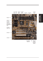
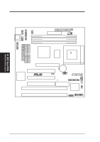
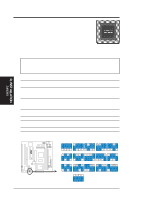
III. INST ALLATION Map of Board III. INSTALLATION Jumpers 1) CLRTC p. 15 Real Time Clock (RTC) RAM 2) VIO p. 15 Voltage Input/Output Selection 4) FS0, FS1, FS2, FS3 p. 16 CPU External (BUS) Frequency Selection 5) BF0, BF1, BF2 p. 16 CPU to BUS Frequency Ratio 6) VID0, VID1, VID2, VID3 p. 18 Voltage Regulator Output Selection Expansion Slots 1) DIMM Sockets 2) CPU ZIF Socket 7 3) SLOT 1, 2 4) PCI 1, 2, 3 p. 19 168-Pin DIMM Memory Expansion Sockets p. 21 Central Processing Unit (CPU) Socket p. 23 16-bit ISA Bus Expansion Slots* p. 23 32-bit PCI Bus Expansion Slots Connectors 1) KB p. 25 Keyboard Connector (5-pin Female) 2) FLOPPY p. 25 Floppy Drive Connector (34-1 pins) 3) PRINTER p. 26 Parallel (Printer) Port Connector (26-1 pins) 4) COM1, COM2 p. 26 Serial Port COM1 & COM2 (10-1 pins) 5) FAN p. 27 Power Supply, Chassis, CPU Fan Power Leads (3 pins) 6) CHASIS p. 27 Chassis Open Alarm Lead (4-1 pins) 7) PRIMARY/SECOND.IDE p. 28 Primary/Secondary IDE Connector (40-1 pins) 8) IDELED p. 28 IDE LED Activity Light (2 pins) 9) ATX p. 29 ATX Motherboard Power Connector (20 pins) 10) PS/2 p. 29 AT Motherboard Power Connector (12 pins) 11) USB/MIR p. 31 USB, Infrared, PS/2 Mouse Module Connector (18-1 pins) 12) IR p. 31 IrDA-compliant Infrared Module Connector (5 pins) 13) MSG.LED (PANEL) p. 31 System Message LED (2 pins) 14) PWR SW. (PANEL) p. 31 ATX Power Switch/Soft Power Switch Lead (2 pins) 15) RESET (PANEL) p. 31 Reset Switch Lead (2 pins) 16) PWR.LED (PANEL) p. 31 System Power LED Lead (3 pins) 17) KEYLOCK (PANEL) p. 31 Keyboard Lock Switch Lead (2 pins) 18) SPEAKER (PANEL) p. 31 Speaker Output Connector (4 pins) 19) WOLCON p. 32 Wake-On-LAN Activity Connector (3 pins) 20) SMB p. 32 SMBus Connector (5-1 pins) 21) AUDIOCON p. 33 Audio Jack Connector (26 pins) 22) SPD0/SPD1/TTL p. 33 Digital Audio Interface (6 pins) 23) AUX p. 34 Stereo Audio In Connector (4 pins) 24) CD1 p. 34 Stereo Audio In Connector (4 pins) *The onboard hardware monitor uses the address 290H-297H so legacy ISA cards must not use this address or else conflicts will occur. ASUS P5A-B User's Manual 13
-
 1
1 -
2
-
3
-
4
-
5
-
6
-
7
-
 8
8 -
 9
9 -
 10
10 -
 11
11 -
 12
12 -
 13
13 -
 14
14 -
 15
15 -
 16
16 -
 17
17 -
 18
18 -
19
-
20
-
21
-
22
-
23
-
24
-
25
-
26
-
27
-
28
-
29
-
30
-
31
-
32
-
33
-
34
-
35
-
36
-
37
-
38
-
39
-
40
-
41
-
42
-
43
-
44
-
45
-
46
-
47
-
48
-
49
-
50
-
51
-
52
-
53
-
54
-
55
-
56
-
57
-
58
-
59
-
60
-
61
-
62
-
63
-
64
-
65
-
66
-
67
-
68
-
69
-
70
-
71
-
72
 |
 |
