Asus P5E3 User Guide - Page 51
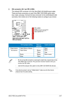
USB 2.0 ports 3 and 4., Optical S/PDIF Out port, USB 2.0 ports 5 and 6. - deluxe wifi ap n bios
 |
UPC - 610839172030
View all Asus P5E3 manuals
Add to My Manuals
Save this manual to your list of manuals |
Page 51 highlights
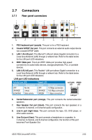
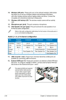
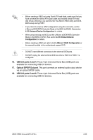
• Before creating a RAID set using Serial ATA hard disks, make sure that you have connected the Serial ATA signal cable and installed Serial ATA hard disk drives; otherwise, you cannot enter the JMicron RAID utility and SATA BIOS setup during POST. • If you intend to create a RAID configuration using this connector, set the J-Micron eSATA/PATA Controller Mode in the BIOS to [RAID]. See section 4.5.3 Onboard Device Configuration for details. • When using hot-plug and NCQ, set the J-Micron eSATA/PATA Controller Mode in the BIOS to [AHCI]. See section 4.5.3 Onboard Device Configuration for details. • Before creating a RAID set, refer to 5.4.3 JMicron® RAID Configuration or the manual bundled in the motherboard support DVD. • DO NOT insert different connectors to the external SATA ports. • DO NOT unplug the external Serial ATA box when a RAID 0 or RAID 1 is configured. 16. USB 2.0 ports 3 and 4. These 4-pin Universal Serial Bus (USB) ports are available for connecting USB 2.0 devices. 17. Optical S/PDIF Out port. This port connects an external audio output device via an optical S/PDIF cable. 18. USB 2.0 ports 5 and 6. These 4-pin Universal Serial Bus (USB) ports are available for connecting USB 2.0 devices. ASUS P5E3 Deluxe/WiFi-AP@n 2-25
-
 1
1 -
2
-
3
-
4
-
5
-
6
-
7
-
8
-
9
-
10
-
11
-
12
-
13
-
14
-
15
-
16
-
17
-
18
-
19
-
20
-
21
-
22
-
23
-
24
-
25
-
26
-
27
-
28
-
29
-
30
-
31
-
32
-
33
-
34
-
35
-
36
-
37
-
38
-
39
-
40
-
41
-
42
-
43
-
44
-
45
-
 46
46 -
 47
47 -
 48
48 -
 49
49 -
 50
50 -
 51
51 -
 52
52 -
 53
53 -
 54
54 -
 55
55 -
 56
56 -
57
-
58
-
59
-
60
-
61
-
62
-
63
-
64
-
65
-
66
-
67
-
68
-
69
-
70
-
71
-
72
-
73
-
74
-
75
-
76
-
77
-
78
-
79
-
80
-
81
-
82
-
83
-
84
-
85
-
86
-
87
-
88
-
89
-
90
-
91
-
92
-
93
-
94
-
95
-
96
-
97
-
98
-
99
-
100
-
101
-
102
-
103
-
104
-
105
-
106
-
107
-
108
-
109
-
110
-
111
-
112
-
113
-
114
-
115
-
116
-
117
-
118
-
119
-
120
-
121
-
122
-
123
-
124
-
125
-
126
-
127
-
128
-
129
-
130
-
131
-
132
-
133
-
134
-
135
-
136
-
137
-
138
-
139
-
140
-
141
-
142
-
143
-
144
-
145
-
146
-
147
-
148
-
149
-
150
-
151
-
152
-
153
-
154
-
155
-
156
-
157
-
158
-
159
-
160
-
161
-
162
-
163
-
164
-
165
-
166
-
167
-
168
-
169
-
170
-
171
-
172
-
173
-
174
-
175
-
176
-
177
-
178
-
179
-
180
-
181
-
182
-
183
-
184
-
185
-
186
-
187
-
188
-
189
-
190
-
191
-
192
-
193
-
194
 |
 |