Asus P5GPL P5GPL English user's manual
Asus P5GPL Manual
 |
View all Asus P5GPL manuals
Add to My Manuals
Save this manual to your list of manuals |
Asus P5GPL manual content summary:
- Asus P5GPL | P5GPL English user's manual - Page 1
P5GPL Motherboard - Asus P5GPL | P5GPL English user's manual - Page 2
express written permission of ASUSTeK COMPUTER INC. ("ASUS"). Product warranty or service will not be extended if: (1) the ASUS HAS BEEN ADVISED OF THE POSSIBILITY OF SUCH DAMAGES ARISING FROM ANY DEFECT OR ERROR IN THIS MANUAL OR PRODUCT. SPECIFICATIONS AND INFORMATION CONTAINED IN THIS MANUAL - Asus P5GPL | P5GPL English user's manual - Page 3
ix P5GPL specifications summary x Chapter 1: Product introduction 1.1 Welcome 1-2 1.2 Package contents 1-2 1.3 Special features 1-3 1.3.1 Product highlights 1-3 1.3.2 ASUS Proactive features 1-5 1.3.3 Innovative ASUS features 1-5 1.4 Before you proceed 1-6 1.5 Motherboard overview - Asus P5GPL | P5GPL English user's manual - Page 4
utility 2-4 2.1.4 ASUS CrashFree BIOS 2 utility 2-6 2.1.5 ASUS Update utility 2-8 2.2 BIOS setup program 2-11 2.2.1 BIOS menu screen 2-12 2.2.2 Menu bar 2-12 2.2.3 Navigation keys 2-12 2.2.4 Menu items 2-13 2.2.5 Sub-menu items 2-13 2.2.6 Configuration fields 2-13 2.2.7 Pop-up window 2-13 - Asus P5GPL | P5GPL English user's manual - Page 5
2-34 2.6.3 Security 2-36 2.7 Exit menu 2-38 Chapter 3: Software support 3.1 Installing an operating system 3-2 3.2 Support CD information 3-2 3.2.1 Running the support CD 3-2 3.2.2 Drivers menu 3-3 3.2.3 Utilities menu 3-4 3.2.4 Manuals menu 3-5 3.2.5 ASUS Contact information 3-6 v - Asus P5GPL | P5GPL English user's manual - Page 6
if not installed and used in accordance with manufacturer's instructions, may cause harmful interference to radio communications. However, there harmful interference to radio or television reception, which can be determined by turning the equipment off and on, the user is encouraged to try to - Asus P5GPL | P5GPL English user's manual - Page 7
Contact a qualified service technician or your retailer. Operation safety • Before installing the motherboard and adding devices on it, carefully read all the manuals that came with . • If you encounter technical problems with the product, contact a qualified service technician or your retailer. vii - Asus P5GPL | P5GPL English user's manual - Page 8
the BIOS parameters are also provided. • Chapter 3: Software support This chapter describes the contents of the support CD that comes with the motherboard package. Where to find more information Refer to the following sources for additional information and for product and software updates. 1. ASUS - Asus P5GPL | P5GPL English user's manual - Page 9
following symbols used throughout this manual. D A N G E R / W A R N I N G : Information to prevent injury to yourself when trying to complete a task. C A U T I O N : Information to prevent damage to the components when trying to complete a task. I M P O R T A N T : Instructions that you MUST follow - Asus P5GPL | P5GPL English user's manual - Page 10
P5GPL specifications summary CPU LGA775 socket for Intel® Pentium® 4/Celeron® processor Compatible with the Intel® PCG 04A and 04B processors Supports Intel® Hyper-Threading Technology Chipset Northbridge: Intel® 915PL Southbridge: Intel® ICH6 F r o n t S i d e B u s 800/533 MHz Memory Dual- - Asus P5GPL | P5GPL English user's manual - Page 11
panel audio connector 1 x S/PDIF out connector System panel connector ATX power supply (with 24-pin and 4-pin 12 V plugs) ATX 12 V 2.0 compliant ATX form factor: 12 in x 9.6 in (30.5 cm x 24.4 cm) Device drivers ASUS PC Probe ASUS Live Update utility Anti-virus utility (OEM version) *Specifications - Asus P5GPL | P5GPL English user's manual - Page 12
xii - Asus P5GPL | P5GPL English user's manual - Page 13
This chapter describes the motherboard features and the new technologies it supports. 1Product introduction ASUS P5GPL 1-1 - Asus P5GPL | P5GPL English user's manual - Page 14
following items. Motherboard ASUS P5GPL motherboard Cables 2 x Serial ATA signal cables 2 x Serial ATA power cables 1 x Ultra DMA/100 cables Floppy disk drive cable Accessories I/O shield A p p l i c a t i o n C D s ASUS motherboard support CD D o c u m e n t a t i o n User guide If any of - Asus P5GPL | P5GPL English user's manual - Page 15
. Serial ATA technology The motherboard supports the Serial ATA technology through the Serial ATA interfaces and the Intel® ICH6. The SATA specification allows for thinner, more flexible cables with lower pin count, reduced voltage requirement, and up to 150 MB/s data transfer rate. ASUS P5GPL 1-3 - Asus P5GPL | P5GPL English user's manual - Page 16
The S/PDIF technology turns your computer into a high-end entertainment system with digital connectivity to powerful audio and speaker systems. See pages 1-27 and 1-33 for details. USB 2.0 technology The motherboard implements the Universal Serial Bus (USB) 2.0 specification, dramatically increasing - Asus P5GPL | P5GPL English user's manual - Page 17
® chipset by shortening the latency time between the CPU and the system memory. See page 2-25 for details. 1.3.3 Innovative ASUS features CrashFree BIOS 2 This feature allows you to restore the original BIOS data from the support CD in case when the BIOS codes and data are corrupted. This protection - Asus P5GPL | P5GPL English user's manual - Page 18
a reminder that you should shut down the system and unplug the power cable before removing or plugging in any motherboard component. The illustration below shows the location of the onboard LED. P5GPL P5GPL Onboard LED SB_PWR ON Standby Power OFF Powered Off 1-6 Chapter 1: Product introduction - Asus P5GPL | P5GPL English user's manual - Page 19
chassis as indicated in the image below. 1.5.2 Screw holes Place nine (9) screws into the holes indicated by circles to secure the motherboard to the chassis. Do not overtighten the screws! Doing so can damage the motherboard. Place this side towards the rear of the chassis P5GPL ASUS P5GPL 1-7 - Asus P5GPL | P5GPL English user's manual - Page 20
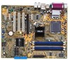
FLOPPY EATXPWR 30.5cm (12.0in) 1.5.3 Motherboard layout 24.5cm (9.6in) PS/2KBMS KBPWR T: Mouse B: Keyboard SPDIF_O ATX12V LGA775 USBPW12 USBPW34 PWR_FAN PCIEX1_1 Intel R 915PL CPU_FAN PCIEX16 PCI1 CD P5GPL PCI2 ALC880 SPDIF_OUT PCI3 AAFP PCIEX1_2 CR2032 3V Lithium Cell CMOS Power - Asus P5GPL | P5GPL English user's manual - Page 21
Unit (CPU) The motherboard comes with a surface mount LGA775 socket designed for the Intel® Pentium® 4 processor in the 775-land package. • Your boxed Intel® Pentium® 4 LGA775 processor package should come with installation instructions for the CPU, fan and heatsink assembly. If the instructions in - Asus P5GPL | P5GPL English user's manual - Page 22
. 4. Lift the load plate with your thumb and forefinger to a 100º angle (A), then push the PnP cap from the load plate window to remove (B). B A Load plate 5. Position the CPU over the socket, making sure that the gold triangle is on the bottom-left corner of the socket. The socket alignment key - Asus P5GPL | P5GPL English user's manual - Page 23
connectors on the socket and damaging the CPU! Notes on Intel® Hyper-Threading Technology • This motherboard supports Intel® Pentium® 4 CPUs in the 775-land package with Hyper-Threading Technology. • Hyper-Threading Technology is supported under Windows® XP/2003 Server and Linux 2.4.x (kernel) and - Asus P5GPL | P5GPL English user's manual - Page 24
thermal condition and performance. • Install the motherboard to the chassis before you install the CPU fan and heatsink assembly • When you buy a boxed Intel® Pentium® 4 processor, the package includes the CPU fan and heatsink assembly. If you buy a CPU separately, make sure that you use only - Asus P5GPL | P5GPL English user's manual - Page 25
connect the CPU fan cable to the connector on the motherboard labeled CPU_FAN. CPU_FAN GND P5GPL CPU FAN PWR CPU FAN IN CPU FAN PWM P5GPL CPU fan connector Do not forget to connect the CPU fan connector! Hardware monitoring errors can occur if you fail to plug this connector. ASUS P5GPL 1-13 - Asus P5GPL | P5GPL English user's manual - Page 26
heatsink and fan To uninstall the CPU heatsink and fan: 1. Disconnect the CPU fan cable from the connector on the motherboard labeled CPU_FAN. 2. Rotate each fastener counterclockwise. 3. Pull up two fasteners at a time in a diagonal sequence to disengage the heatsink B and fan assembly from - Asus P5GPL | P5GPL English user's manual - Page 27
4. Remove the heatsink and fan assembly from the motherboard. 5. Rotate each fastener clockwise to reset the orientation. When reset, each fastener should be oriented as shown, with the narrow groove directed outward. ASUS P5GPL 1-15 - Asus P5GPL | P5GPL English user's manual - Page 28
motherboard comes with four 184-pin Double Data Rate (DDR) Dual Inline Memory Modules (DIMM) sockets. The following figure illustrates the location of the sockets: P5GPL P5GPL in Table 1. • Due to chipset limitation, this motherboard supports a maximum of 2GB total memory and two (2) ranks - Asus P5GPL | P5GPL English user's manual - Page 29
and DDR_B2 Table 2 DDR400 Qualified Vendors List Size Vendor Model Brand Side(s) Component DIMM support AB C 256MB 512MB 256MB 512MB 256MB 512MB 1024MB 1024MB 256MB 256MB 512MB 512MB 256MB 512MB TCC4 K4H560838E-TCCC DD2508AMTA DD2508AMTA (Continued on the next page) ASUS P5GPL 1-17 - Asus P5GPL | P5GPL English user's manual - Page 30
N/A N/A PSC PSC N/A CEON CEON Side(s) Component DIMM support AB C SS N2DS25680CT-5T DS N2DS25680CT-5T SS VT56DD32M8PC-5 blue slots or the black slots as one pair of Dual-channel memory configuration. C - support for 4 modules inserted into the blue and black slots as two pairs of Dual-channel - Asus P5GPL | P5GPL English user's manual - Page 31
components. Failure to do so may cause severe damage to both the motherboard and the components. 1. Unlock a DIMM socket by pressing the retaining clips retaining clips outward to unlock the DIMM. 1 1 DDR DIMM notch Support the DIMM lightly with your fingers when pressing the retaining clips. The - Asus P5GPL | P5GPL English user's manual - Page 32
cards that they support. Make sure to and damage motherboard components. motherboard is already installed in a chassis). 3. Remove the bracket opposite the slot that you intend to use. Keep Turn on the system and change the necessary BIOS settings, if any. See Chapter 2 for information on BIOS - Asus P5GPL | P5GPL English user's manual - Page 33
motherboard PCI slot 1 PCI slot 2 PCI slot 3 PCI E x1 slot 1 PCI E x1 slot 2 PCI E x1 slot 3 PCI E x16 slot Onboard USB controller 1 Onboard USB controller 2 Onboard USB controller 3 Onboard USB controller 4 Onboard USB 2.0 controller Onboard LAN Onboard Azalia audio that the drivers support "Share - Asus P5GPL | P5GPL English user's manual - Page 34
1.8.4 PCI slots The PCI slots support cards such as a LAN card, SCSI card, USB card, and other cards that comply with PCI specifications. The figure shows a LAN card installed on a PCI slot. 1.8.5 PCI Express x16 slot This motherboard supports PCI Express x16 graphic cards that comply with the PCI - Asus P5GPL | P5GPL English user's manual - Page 35
RTC RAM setting You do not need to clear the RTC when the system hangs due to overclocking. For system failure due to overclocking, use the C.P.R. (CPU Parameter Recall) feature. Shut down and reboot the system so the BIOS can automatically reset parameter settings to default values. ASUS P5GPL - Asus P5GPL | P5GPL English user's manual - Page 36
and USBPWR34 jumpers are for the rear USB ports. The USBPWR56 and USBPWR78 jumper is for the internal USB connectors that you can connect to additional USB ports. USBPW12 USBPW34 12 23 +5V +5VSB (Default) USBPW56 P5GPL USBPW78 12 23 P5GPL USB device wake-up +5V (Default) +5VSB • The - Asus P5GPL | P5GPL English user's manual - Page 37
the Space Bar). This feature requires an ATX power supply that can supply at least 1A on the +5VSB lead, and a corresponding setting in the BIOS. KBPWR 12 23 +5V +5VSB (Default) P5GPL P5GPL Keyboard power setting ASUS P5GPL 1-25 - Asus P5GPL | P5GPL English user's manual - Page 38
P S / 2 m o u s e p o r t ( g r e e n ) . This port is for a PS/2 mouse. 2 . P a r a l l e l p o r t . This 25-pin port connects a parallel printer, a LAN port 4 . R e a r S p e a k e r O u t p o r t ( g r a y ) . This port connects the rear speakers on a 4-channel, 6-channel, or 8-channel audio - Asus P5GPL | P5GPL English user's manual - Page 39
l c o n n e c t o r . This 9-pin COM1 port is for serial devices. 1 3 . C o a x i a l S / P D I F O u t p o r t . This port connects an external audio output device via a coaxial S/PDIF cable. 1 4 . P S / 2 k e y b o a r d p o r t ( p u r p l e ) . This port is for a PS/2 keyboard. ASUS P5GPL 1-27 - Asus P5GPL | P5GPL English user's manual - Page 40
PIN 1 P5GPL Floppy disk drive connector 2 . Primary IDE connector (40-1 pin PRI_IDE) This connector is for an Ultra DMA 100/66 signal cable. The Ultra DMA 100/66 signal cable has three connectors: a blue connector for the primary IDE connector on the motherboard, a black connector for an Ultra - Asus P5GPL | P5GPL English user's manual - Page 41
RSATA_RXP3 RSATA_RXN3 GND Important notes on Serial ATA • Install the Windows® 2000 Service Pack 4 or the Windows® XP Service Pack1 before using Serial ATA. • Plug your Serial ATA boot disk on the master port (SATA1 and SATA2) to support S3 function. Refer to the table below for details. Serial - Asus P5GPL | P5GPL English user's manual - Page 42
flow inside the system may damage the motherboard components. These are not jumpers! DO NOT place jumper caps on the fan connectors. CPU_FAN GND CPU FAN PWR CPU FAN IN CPU FAN PWM PWR_FAN GND +12V Rotation P5GPL CHA_FAN P5GPL Fan connectors 6 . USB connectors (10-1 pin USB56, USB78) These connectors - Asus P5GPL | P5GPL English user's manual - Page 43
recommended that you use an ATX 12 V Specification 2.0-compliant power supply unit (PSU) with a Specification 2.0-compliant PSU passed the motherboard power requirement test with the following configuration: CPU ATX12V +12V DC GND +12V DC GND P5GPL P5GPL ATX power connectors EATXPWR +3 Volts -12 - Asus P5GPL | P5GPL English user's manual - Page 44
connector (4-pin CD) This connector is for the 4-pin audio cable that connects to the audio connector at the back of the optical drive. P5GPL CD P5GPL CD audio connector 9 . Chassis intrusion connector (4-1 pin CHASSIS) This connector is for a chassis-mounted intrusion detection sensor or switch - Asus P5GPL | P5GPL English user's manual - Page 45
panel audio I/O module that supports either HD Audio or legacy AC '97 audio standard. Connect one end of the front panel audio P5GPL P5GPL Analog front panel connector • Connect a high-definiton front panel audio module to this connector to avail the high-definition audio features of the motherboard - Asus P5GPL | P5GPL English user's manual - Page 46
supports several chassis-mounted functions. PLED SPEAKER PLED+ PLED+5V Ground Ground Speaker PANEL P5GPL IDE_LED+ IDE_LED- PWR Ground Reset Ground P5GPL Pressing the power button turns the system ON or puts the system in SLEEP or SOFT-OFF mode depending on the BIOS settings. Pressing the power - Asus P5GPL | P5GPL English user's manual - Page 47
This chapter tells how to change the system settings through the BIOS Setup menus. Detailed descriptions of the BIOS parameters are also provided. 2 BIOS setup ASUS P5GPL 2-1 - Asus P5GPL | P5GPL English user's manual - Page 48
using a floppy disk during POST.) 3. A S U S C r a s h F r e e B I O S 2 (Updates the BIOS using a bootable floppy disk or the motherboard support CD when the BIOS file fails or gets corrupted.) 4. A S U S U p d a t e (Updates the BIOS in Windows® environment.) Refer to the corresponding sections - Asus P5GPL | P5GPL English user's manual - Page 49
Visit the ASUS website (www.asus.com) to download the latest BIOS file for the motherboard and rename the same to P 5 G P L . R O M. 2. Save the BIOS file to a floppy disk, then restart the system. 3. Press + during POST to display the following. EZFlash starting BIOS update Checking for - Asus P5GPL | P5GPL English user's manual - Page 50
least 600 KB free space to save the file. • The succeeding BIOS screens are for reference only. The actual BIOS screen displays may not be exactly the same as shown. 1. Copy the AFUDOS utility (afudos.exe) from the motherboard support CD to the bootable floppy disk you created earlier. 2. Boot the - Asus P5GPL | P5GPL English user's manual - Page 51
Updating the BIOS file To update the BIOS file using the AFUDOS utility: 1. Visit the ASUS website (www.asus.com) and download the latest BIOS file for the motherboard. Save the BIOS file to a bootable floppy disk. Write the BIOS filename on a piece of paper. You need to type the exact BIOS filename - Asus P5GPL | P5GPL English user's manual - Page 52
2 utility The ASUS CrashFree BIOS 2 is an auto recovery tool that allows you to restore the BIOS file when it fails or gets corrupted during the updating process. You can update a corrupted BIOS file using the motherboard support CD or the floppy disk that contains the updated BIOS file. • Prepare - Asus P5GPL | P5GPL English user's manual - Page 53
while updating the BIOS! Doing so can cause system boot failure! 4. Restart the system after the utility completes the updating process. The recovered BIOS may not be the latest BIOS version for this motherboard. Visit the ASUS website (www.asus.com) to download the latest BIOS file. ASUS P5GPL - Asus P5GPL | P5GPL English user's manual - Page 54
you to manage, save, and update the motherboard BIOS in Windows® environment. The ASUS Update utility allows you to: • Save the current BIOS file • Download the latest BIOS file from the Internet • Update the BIOS from an updated BIOS file • Update the BIOS directly from the Internet, and • View - Asus P5GPL | P5GPL English user's manual - Page 55
Updating the BIOS through the Internet To update the BIOS through the Internet: 1. Launch the ASUS Update utility from the Windows® desktop by clicking S t a r t > P r o g r a m s > A S U S > A S U S U p d a t e > A S U S U p d a t e. The ASUS Update main window appears. 2. Select U p d a t e B I O - Asus P5GPL | P5GPL English user's manual - Page 56
to download. Click Next. 5. Follow the screen instructions to complete the update process. The ASUS Update utility is capable of updating itself through the Internet. Always update the utility to avail all its features. Updating the BIOS through a BIOS file To update the BIOS through a BIOS file - Asus P5GPL | P5GPL English user's manual - Page 57
the Exit Menu. See section "2.7 Exit Menu." • The BIOS setup screens shown in this section are for reference purposes only, and may not exactly match what you see on your screen. • Visit the ASUS website (www.asus.com) to download the latest BIOS file for this motherboard and . ASUS P5GPL 2-11 - Asus P5GPL | P5GPL English user's manual - Page 58
Master IDE Configuration System Information [11:10:19] [Thu 03/27/2003] [1.44M, 3.5 in] [English] :[ST320413A] :[ASUS CD-S340] :[Not Detected] :[Not Detected] :[Not Detected] :[Not Detected] Use [ENTER], [TAB] or [SHIFT-TAB keys differ from one screen to another. 2-12 Chapter 2: BIOS setup - Asus P5GPL | P5GPL English user's manual - Page 59
2.2.4 Menu items The highlighted item on the menu bar displays the specific items for that menu. For example, selecting M a i n shows the Main menu items. The other items Screen Select Item +- Change Option F1 General Help F10 Save and Exit ESC Exit Pop-up window Scroll bar ASUS P5GPL 2-13 - Asus P5GPL | P5GPL English user's manual - Page 60
an overview of the basic system information. Refer to section "2.2.1 BIOS menu screen" for information on the menu screen items and in.] [2.88M, 3.5 in.] 2.3.4 Language [English] Allows you to choose the BIOS language version from the options. Configuration options: [Français] [German] [English] - Asus P5GPL | P5GPL English user's manual - Page 61
display the IDE device information. Primary IDE Master Device : Hard Disk Vendor : ST320413A Size : 20.0GB LBA Mode : Supported Block Mode : 16 Sectors PIO Mode : Supported appropriate IDE device type. Select CDROM if you are specifically configuring a CD-ROM drive. Select ARMD (ATAPI - Asus P5GPL | P5GPL English user's manual - Page 62
IDE Configuration Onboard IDE Operate Mode Enhanced Mode Support On IDE Detect Time Out (Sec) [ Windows® 2000/XP/2003 Server. Configuration options: [Disabled] [Compatible Mode] [Enhanced Mode] Enhanced Mode Support and encounter problems, revert to the default setting S A T A m o d - Asus P5GPL | P5GPL English user's manual - Page 63
: 04/07/04 Processor Type Speed Count : Genuine Intel(R) CPU 3.20GHz : 2800 MHz : 1 System Memory Size : 512MB AMI BIOS Displays the auto-detected BIOS information Processor Displays the auto-detected CPU specification System Memory Displays the auto-detected system memory ASUS P5GPL 2-17 - Asus P5GPL | P5GPL English user's manual - Page 64
LAN Cable Status USB Configuration CPU Configuration Chipset Onboard Devices Configuration PCI PnP Configure CPU CPU Lock Free [Auto] Allows you to adjust the CPU multiplier to 14x. Setting this item to [Auto] allows the motherboard to automatically reduce the CPU S - the ASUS AI Non-delay - Asus P5GPL | P5GPL English user's manual - Page 65
a threshold between light and heavy CPU loading. S e n s i t i v e - activates overclocking on a light CPU loading. H e a v y L o a d - activates overclocking on a heavy CPU loading. The following item appears only options vary depending on the T u r b o N O S item setting. ASUS P5GPL 2-19 - Asus P5GPL | P5GPL English user's manual - Page 66
only when the AI Overclocking item is set to [AI N.O.S.] or [Manual]. Memory Voltage [Auto] Allows selection of the DDR SDRAM operating voltage frequency) multiplied by the bus multiple equals the CPU speed. The value of this item is auto-detected by BIOS. The values range from 100 to 400. Refer - Asus P5GPL | P5GPL English user's manual - Page 67
PCI Clock Synchronization mode. Configuration options: [To CPU] [33.33MHz] [Auto] 2.4.2 LAN Cable Status The items in this menu displays the status of the Local Area Network (LAN) cable. POST Check LAN cable LAN Cable Status Pair Status Length 1-2 N/A 3-6 N/A 4-5 N/A 7-8 N/A [Disabled - Asus P5GPL | P5GPL English user's manual - Page 68
-related features. Select an item then press to display the configuration options. USB Configuration Module Version - 2.23.2-9.4 USB Devices Enabled: None USB Function Legacy USB Support USB 2.0 Controller USB 2.0 Controller Mode [Enabled] [Auto] [Enabled] [HiSpeed] The Module Version and - Asus P5GPL | P5GPL English user's manual - Page 69
] Disables or enables the microcode updation function. Configuration options: [Disabled] [Enabled] Max CPUID Value Limit [Disabled] Enable this item to boot legacy operating systems that cannot support CPUs with extended CPUID functions. Configuration options: [Disabled] [Enabled] ASUS P5GPL 2-23 - Asus P5GPL | P5GPL English user's manual - Page 70
] [Enabled] Enhanced C1 Control [Auto] When set to [Auto], the BIOS will automatically check the CPU's capability to enable the C1E support. In C1E mode, the CPU power consumption is lower when idle. Configuration options: [Auto] [Disabled] CPU Internal Thermal Control [Auto] Disables or sets the - Asus P5GPL | P5GPL English user's manual - Page 71
PCI Express Graphics root control. Configuration options: [Auto] [Disabled] [Enabled] Slot Power [Auto] Sets the slot operating power. Configuration options: [Auto] [Light] [Normal] [Heavy] [Heavier] ASUS P5GPL 2-25 - Asus P5GPL | P5GPL English user's manual - Page 72
Disable High Definition Audio Controller HD Audio Controller [Enabled] Enables or disables the High Definition/AC'97 CODEC. Configuration options: [Enabled] [Disabled] OnBoard LAN [Enabled] r a l l e l P o r t M o d e is set to E P P. Configuration options: [1.9] [1.7] 2-26 Chapter 4: BIOS setup - Asus P5GPL | P5GPL English user's manual - Page 73
Save and Exit ESC Exit Plug and Play O/S [No] When set to [No], BIOS configures all the devices in the system. When set to [Yes] and if you install VGA [Yes] When set to [Yes], BIOS assigns an IRQ to PCI VGA card if the card requests for an IRQ. When set to [No], BIOS does not assign an IRQ to the - Asus P5GPL | P5GPL English user's manual - Page 74
Configuration options: [Disabled] [Enabled] PCI IDE BusMaster [Enabled] Allows BIOS to use PCI bus mastering when reading/writing to IDE devices. Configuration ] IRQ-xx assigned to [PCI Device] When set to [PCI Device], the specific IRQ is free for use of PCI/PnP devices. When set to [Reserved], - Asus P5GPL | P5GPL English user's manual - Page 75
] Allows you to enable or disable the Advanced Configuration and Power Interface (ACPI) support in the Application-Specific Integrated Circuit (ASIC). When set to Enabled, the ACPI APIC table pointer is included in the RSDT pointer list. Configuration options: [Disabled] [Enabled] ASUS P5GPL 2-29 - Asus P5GPL | P5GPL English user's manual - Page 76
] Power On By PS/2 Keyboard [Disabled] Keyboard Wakeup Password : Not Installed Power On By PS/2 Mouse [Disabled] 01] ~ [59] RTC Alarm Second [30] Sets the RTC alarm second. Use the plus (+) or minus (-) keys to adjust the values. Configuration options: [00] [01] ~ [59] 2-30 Chapter 2: BIOS - Asus P5GPL | P5GPL English user's manual - Page 77
on the system through a PCI LAN or modem card. This feature requires an ATX power supply that provides at least 1A on the +5VSB lead. Configuration options: [Disabled] [Enabled] Power On By PS/2 Keyboard [Disabled] Allows you to use specific keys on the keyboard to turn on the system. This feature - Asus P5GPL | P5GPL English user's manual - Page 78
[N/A] The onboard hardware monitor automatically detects and displays the CPU fan speed in rotations per minute (RPM). If the fan is not connected to the motherboard, the field shows N/A. CPU Q-Fan Control [Disabled] Allows you to enable or disable the ASUS Q-Fan feature that smartly adjusts the fan - Asus P5GPL | P5GPL English user's manual - Page 79
CPU installed. Chassis Fan Speed [xxxxRPM] or [N/A] The onboard hardware monitor automatically detects and displays the chassis fan speed in rotations per minute (RPM). If the fan is not connected to the chassis, the specific an item then press to display the sub-menu. APM Configuration Boot - Asus P5GPL | P5GPL English user's manual - Page 80
Boot Device [1st FLOPPY DRIVE] [PM-ST330620A] [PS-ASUS CD-S360] 1st ~ xxth Boot Device [1st Display Mode Bootup Num-Lock PS/2 Mouse Support Wait For 'F1' If Error Hit 'DEL' Message Display Interrupt 19 Capture [Enabled] [Enabled] [Force BIOS] [On] [Auto] [Enabled] [Enabled] [Disabled] Allows BIOS - Asus P5GPL | P5GPL English user's manual - Page 81
Display Mode [Force BIOS] Sets the display mode for option ROM. Configuration options: [Force BIOS] [Keep Current] Bootup Num-Lock [On] Allows you to select the power-on state for the NumLock. Configuration options: [Off] [On] PS/2 Mouse Support [Auto] Allows you to enable or disable support for PS - Asus P5GPL | P5GPL English user's manual - Page 82
settings. Select an item then press to display the configuration options. Security Settings Supervisor Password : Not Installed Uninstalled" appears. If you forget your BIOS password, you can clear clear it by erasing the CMOS Real Time Clock (RTC) RAM. See section "1.9 Jumpers" for - Asus P5GPL | P5GPL English user's manual - Page 83
. To change the user password, follow the same steps as in setting a user password. Clear User Password Select this item to clear the user password. ASUS P5GPL 2-37 - Asus P5GPL | P5GPL English user's manual - Page 84
optimal or failsafe default values for the BIOS items, and save or discard your changes to the BIOS items. Exit Options Exit & Save Changes RAM. An onboard backup battery sustains the CMOS RAM so it stays on even when the PC is turned off. When you select this option, a confirmation window appears - Asus P5GPL | P5GPL English user's manual - Page 85
fields other than System Date, System Time, and Password, the BIOS asks for a confirmation before exiting. Discard Changes This option on the Setup menus. When you select this option or if you press , a confirmation window appears. Select O k to load default values. Select E x i t & S a v - Asus P5GPL | P5GPL English user's manual - Page 86
2-40 Chapter 2: BIOS setup - Asus P5GPL | P5GPL English user's manual - Page 87
This chapter describes the contents of the support CD that comes with the motherboard package. 3 Software support ASUS P5GPL 3-1 - Asus P5GPL | P5GPL English user's manual - Page 88
that you install Windows® 2000 Service Pack 4 or the Windows® XP Service Pack 1 or later versions before installing the drivers for better compatibility and system stability. 3.2 Support CD information The support CD that came with the motherboard package contains the drivers, software applications - Asus P5GPL | P5GPL English user's manual - Page 89
Driver Executes the wizard to install the Realtek® ALC880 audio driver and application. Marvell Yukon Gigabit Ethernet Driver Installs the Marvell® Yukon 88E8053 PCI Express™ Gigabit LAN driver that provides up to 1000 Mbps data transfer rates. USB 2.0 Driver Installs the USB 2.0 driver. ASUS P5GPL - Asus P5GPL | P5GPL English user's manual - Page 90
supports. ASUS PC Probe This smart utility monitors the fan speed, CPU temperature, and system voltages, and alerts you of any detected problems. This utility helps you keep your computer in healthy operating condition. ASUS Update The ASUS Update utility allows you to update the motherboard BIOS - Asus P5GPL | P5GPL English user's manual - Page 91
® Reader from the U t i l i t i e s m e n u before opening a user manual file. • Some user manuals listed in this menu may not be applicable for this motherboard model. Intel LGA775 CPU Install User's Manual Allows you to open the Intel® LGA775 CPU installation user's manual. ASUS P5GPL 3-5 - Asus P5GPL | P5GPL English user's manual - Page 92
3.2.5 ASUS Contact information Click the C o n t a c t tab to display the ASUS contact information. You can also find this information on the inside front cover of this user guide. 3-6 Chapter 3: Software support
-
 1
1 -
 2
2 -
 3
3 -
 4
4 -
 5
5 -
 6
6 -
 7
7 -
8
-
9
-
10
-
11
-
12
-
13
-
14
-
15
-
16
-
17
-
18
-
19
-
20
-
21
-
22
-
23
-
24
-
25
-
26
-
27
-
28
-
29
-
30
-
31
-
32
-
33
-
34
-
35
-
36
-
37
-
38
-
39
-
40
-
41
-
42
-
43
-
44
-
45
-
46
-
47
-
48
-
49
-
50
-
51
-
52
-
53
-
54
-
55
-
56
-
57
-
58
-
59
-
60
-
61
-
62
-
63
-
64
-
65
-
66
-
67
-
68
-
69
-
70
-
71
-
72
-
73
-
74
-
75
-
76
-
77
-
78
-
79
-
80
-
81
-
82
-
83
-
84
-
85
-
86
-
87
-
88
-
89
-
90
-
91
-
92
 |
 |

Motherboard
P5GPL