Asus P5P41TD User Manual - Page 22
System memory
 |
View all Asus P5P41TD manuals
Add to My Manuals
Save this manual to your list of manuals |
Page 22 highlights
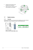
4. Carefully remove the heatsink and fan assembly from the motherboard. 5. Rotate each fastener clockwise to ensure correct orientation when reinstalling. 1.7 System memory 1.7.1 Overview The motherboard comes with four Double Data Rate 3 (DDR3) Dual Inline Memory Modules (DIMM) sockets. The figure illustrates the location of the DDR3 DIMM sockets: DIMM_A1 DIMM_A2 DIMM_B1 DIMM_B2 P5P41TD Channel Channel A Channel B Sockets DIMM_A1 and DIMM_A2 DIMM_B1 and DIMM_B2 P5P41TD 240-pin DDR3 DIMM sockets 1-12 Chapter 1: Product introduction
-
 1
1 -
2
-
3
-
4
-
5
-
6
-
7
-
8
-
9
-
10
-
11
-
12
-
13
-
14
-
15
-
16
-
 17
17 -
 18
18 -
 19
19 -
 20
20 -
 21
21 -
 22
22 -
 23
23 -
 24
24 -
 25
25 -
 26
26 -
 27
27 -
28
-
29
-
30
-
31
-
32
-
33
-
34
-
35
-
36
-
37
-
38
-
39
-
40
-
41
-
42
-
43
-
44
-
45
-
46
-
47
-
48
-
49
-
50
-
51
-
52
-
53
-
54
-
55
-
56
-
57
-
58
 |
 |

1-12
Chapter 1: Product introduction
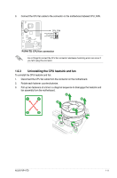
P5P41TD
P5P41TD 240-pin DDR3 DIMM sockets
DIMM_A1
DIMM_A2
DIMM_B1
DIMM_B2
1.7
System memory
1.7.1
Overview
The motherboard comes with four Double Data Rate 3 (DDR3) Dual Inline Memory Modules
(DIMM) sockets. The figure illustrates the location of the DDR3 DIMM sockets:
Channel
Sockets
Channel A
DIMM_A1 and DIMM_A2
Channel B
DIMM_B1 and DIMM_B2
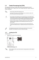
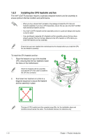
4.
Carefully remove the heatsink and fan
assembly from the motherboard.
5.
Rotate each fastener clockwise to ensure
correct orientation when reinstalling.