Asus P5V-VM Ultra Motherboard Installation Guide - Page 37
P5V-VM ULTRA ATX Power Connectors, P5V-VM ULTRA Speaker Out Connector
 |
View all Asus P5V-VM Ultra manuals
Add to My Manuals
Save this manual to your list of manuals |
Page 37 highlights
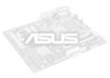
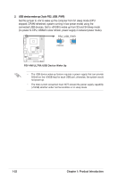
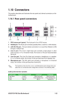
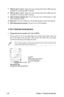
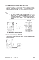
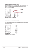
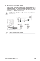
5. ATX power connectors (24-pin EATXPWR, 4-pin ATX12V) These connectors are for ATX power supply plugs. The plugs from the power supply are designed to fit these connectors in only one orientation. Find the proper orientation and push down firmly until the connectors fit completely. • Do not forget to connect the 4-pin ATX +12V power plug; otherwise, the system does not boot up. • Make sure that your ATX 12V power supply can provide 12A on the +12V lead and at least 1A on the +5-volt standby lead (+5VSB). The minimum recommended wattage is 300 W, or 350 W for a fully configured system. The system can become unstable or will not boot up if the power is inadequate. EATXPWR +3 Volts +12 Volts +12 Volts +5V Standby P5V-VM ULTRA ATX12V Power OK Ground +5 Volts +12V DC +12V DC Ground GND GND +5 Volts Ground +3 Volts +3 Volts P5V-VM ULTRA ATX Power Connectors Ground +5 Volts +5 Volts +5 Volts -5 Volts Ground Ground Ground PSON# Ground -12 Volts +3 Volts 6. Speaker out connector (4-pin SPEAKER) This connector is for the case-mounted speaker and allows you to hear system beeps and warnings. P5V-VM ULTRA SPEAKER Speaker Out GND GND +5V 1 P5V-VM ULTRA Speaker Out Connector ASUS P5V-VM Ultra Motherboard 1-27
-
 1
1 -
2
-
3
-
4
-
5
-
6
-
7
-
8
-
9
-
10
-
11
-
12
-
13
-
14
-
15
-
16
-
17
-
18
-
19
-
20
-
21
-
22
-
23
-
24
-
25
-
26
-
27
-
28
-
29
-
30
-
31
-
 32
32 -
 33
33 -
 34
34 -
 35
35 -
 36
36 -
 37
37 -
 38
38 -
 39
39 -
 40
40 -
 41
41 -
 42
42 -
43
-
44
-
45
-
46
-
47
-
48
-
49
-
50
-
51
-
52
-
53
-
54
-
55
-
56
-
57
-
58
-
59
-
60
-
61
-
62
-
63
-
64
-
65
-
66
-
67
-
68
-
69
-
70
-
71
-
72
-
73
-
74
-
75
-
76
-
77
-
78
 |
 |