Asus P7P55-M TPM User Guide - Page 33
Connectors
 |
View all Asus P7P55-M TPM manuals
Add to My Manuals
Save this manual to your list of manuals |
Page 33 highlights
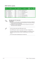
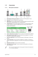
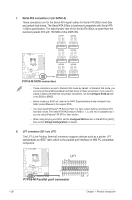
1.11 Connectors 1.11.1 Rear panel connectors 1 3 2 4 56 78 14 13 12 11 10 9 1. PS/2 Keyboard / Mouse port (purple). This port is for a PS/2 keyboard / mouse. 2. Serial port. This 9-pin COM port is for serial devices. 3. IEEE1394 port. This 6-pin IEEE 1394a port provides high-speed connectivity for audio/ video devices, storage peripherals, PCs, or portable devices. 4. LAN (RJ-45) port. This port allows Gigabit connection to a Local Area Network (LAN) through a network hub. Refer to the table below for the LAN port LED indications. LAN port LED indications ACT/LINK LED Status Description OFF No link ORANGE Linked BLINKING Data activity SPEED LED Status OFF ORANGE GREEN Description 10 Mbps connection 100 Mbps connection 1 Gbps connection ACT/LINK SPEED LED LED LAN port 5. Center / Subwoofer port (orange). This port connects the center/subwoofer speakers. 6. Rear Speaker Out port (black). This port connects the rear speakers in a 4-channel, 6-channel, or 8-channel audio configuration. 7. Line In port (light blue). This port connects the tape, CD, DVD player, or other audio sources. 8. Line Out port (lime). This port connects a headphone or a speaker. In 4-channel, 6channel, and 8-channel configurations, the function of this port becomes Front Speaker Out. 9. Microphone port (pink). This port connects a microphone. 10. Side Speaker Out port (gray). This port connects the side speaker in an 8-channel audio configuration. Refer to the audio configuration table on the next page for the function of the audio ports in 2, 4, 6, or 8-channel configuration. ASUS P7P55-M 1-23
-
 1
1 -
2
-
3
-
4
-
5
-
6
-
7
-
8
-
9
-
10
-
11
-
12
-
13
-
14
-
15
-
16
-
17
-
18
-
19
-
20
-
21
-
22
-
23
-
24
-
25
-
26
-
27
-
 28
28 -
 29
29 -
 30
30 -
 31
31 -
 32
32 -
 33
33 -
 34
34 -
 35
35 -
 36
36 -
 37
37 -
 38
38 -
39
-
40
-
41
-
42
-
43
-
44
-
45
-
46
-
47
-
48
-
49
-
50
-
51
-
52
-
53
-
54
-
55
-
56
-
57
-
58
-
59
-
60
-
61
-
62
-
63
-
64
-
65
-
66
-
67
-
68
 |
 |
