Asus PRIME H770-PLUS Users Manual English - Page 16
Storage Device Activity LED header HDD_LED, Power Button/Soft-off Button header PWRSW
 |
View all Asus PRIME H770-PLUS manuals
Add to My Manuals
Save this manual to your list of manuals |
Page 16 highlights
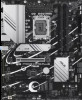
+5V SPDIFOUT GND 15. S/PDIF Out header The S/PDIF Out header allows you to connect the Sony/Philips Digital Interface (S/PDIF) Out module. SPDIF_OUT The S/PDIF module is purchased separately. 16. SPI TPM header This header supports a Trusted Platform Module (TPM) system with a Serial Peripheral Interface (SPI), allowing you to securely store keys, digital certificates, passwords, and data. A TPM system also helps enhance network security, protects digital identities, and ensures platform integrity. TPM PIN 1 VCCSPI S_PLTRST# F2_SPI_CS1#_R +3V_SPI F_SPI_CS0#_R T_SPI_MISO F_SPI_HOLD#_R S_SPI_TPM_IRQ# S_SPI_TPM_CS2# TPM_DETECT_L GND T_SPI_CLK T_SPI_MOSI The TPM module is purchased separately. 17. System Panel header This header supports several chassis-mounted functions. • System Power LED header (PLED) The 2-pin and/or 3-1 pin headers allow you to connect the System Power LED. The System Power LED lights up when the system is connected to a power source, or when you turn on the system power, and blinks when the system is in sleep mode. • Storage Device Activity LED header (HDD_LED) The 2-pin header allows you to connect the Storage Device Activity LED. The Storage Device Activity LED lights up or blinks when data is read from or written to the storage device or storage device add-on card. • System Warning Speaker header (SPEAKER) The 4-pin header allows you to connect the chassis-mounted system warning speaker. The speaker allows you to hear system beeps and warnings. • Power Button/Soft-off Button header (PWRSW) The 2-pin header allows you to connect the system power button. Press the power button to power up the system, or put the system into sleep or soft-off mode (depending on the operating system settings). • Reset button header (RESET) The 2-pin header allows you to connect the chassis-mounted reset button. Press the reset button to reboot the system. • Chassis intrusion header (CHASSIS) The 2-pin header allows you to connect the chassis-mounted intrusion detection sensor or switch. The chassis intrusion sensor or switch sends a high-level signal to the header when a chassis component is removed or replaced, the signal is then generated as a chassis intrusion event. 1-6 Chapter 1: Product Introduction
-
 1
1 -
2
-
3
-
4
-
5
-
6
-
7
-
8
-
9
-
10
-
 11
11 -
 12
12 -
 13
13 -
 14
14 -
 15
15 -
 16
16 -
 17
17 -
 18
18 -
 19
19 -
 20
20 -
 21
21 -
22
-
23
-
24
-
25
-
26
-
27
-
28
-
29
-
30
-
31
-
32
-
33
-
34
-
35
-
36
-
37
 |
 |
