Asus Pro A520M-C II/CSM Pro A520M-C II Users Manual English - Page 11
M.2 slot Key M, SATA 6Gb/s ports, USB 3.2 Gen 1 header, USB 2.0 heades, Chassis intrusion header
 |
View all Asus Pro A520M-C II/CSM manuals
Add to My Manuals
Save this manual to your list of manuals |
Page 11 highlights
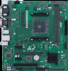
6. M.2 slot (Key M) The M.2 slot allows you to install an M.2 device such as an M.2 SSD module. The M.2 slot supports a PCIe 3.0 x4 mode and SATA mode M Key design and type 2242/2260/2280 storage device. 7. SATA 6Gb/s ports The SATA 6Gb/s ports allow you to connect SATA devices such as optical disc drives and hard disk drives via SATA cables. 8. USB 3.2 Gen 1 header The USB 3.2 Gen 1 header allows you to connect a USB 3.2 Gen 1 module for additional USB 3.2 Gen 1 ports. The USB 3.2 Gen 1 header provides data transfer speed of up to 5 Gb/s. The USB 3.2 Gen 1 module is purchased separately. USB3+5V IntA_P2_SSRXIntA_P2_SSRX+ GND IntA_P2_SSTXIntA_P2_SSTX+ GND IntA_P2_DIntA_P2_D+ PIN 1 USB3+5V IntA_P1_SSRXIntA_P1_SSRX+ GND IntA_P1_SSTXIntA_P1_SSTX+ GND IntA_P1_DIntA_P1_D+ GND USB+5V USB_P3USB_P3+ GND NC 9. USB 2.0 heades The USB 2.0 headers allow you to connect USB modules for additional USB 2.0 ports. The USB 2.0 headers provide data transfer speeds of up to 480 Mb/s. DO NOT connect a 1394 cable to the USB connectors. Doing so will PIN 1 damage the motherboard! The USB 2.0 modules are purchased separately. USB+5V USB_P4USB_P4+ GND 10. Chassis intrusion header This header is for a chassis-mounted intrusion detection sensor or switch. Connect one end of the chassis intrusion sensor or switch cable to this header. The chassis intrusion sensor or switch sends a high-level signal to this header when a chassis component is removed or replaced. The signal is then generated as a chassis intrusion event. +5VSB_MB Chassis Signal GND CHASSIS PIN 1 ASUS Pro A520M-C II 1-3
-
 1
1 -
2
-
3
-
4
-
5
-
 6
6 -
 7
7 -
 8
8 -
 9
9 -
 10
10 -
 11
11 -
 12
12 -
 13
13 -
 14
14 -
 15
15 -
 16
16 -
17
-
18
-
19
-
20
-
21
-
22
-
23
-
24
-
25
-
26
-
27
-
28
-
29
-
30
 |
 |
