Asus Pro A520M-C II/CSM Pro A520M-C II Users Manual English - Page 13
Power button/Soft-off button 2-pin PWR_BTN, System power LED 2-pin +PWR_LED
 |
View all Asus Pro A520M-C II/CSM manuals
Add to My Manuals
Save this manual to your list of manuals |
Page 13 highlights
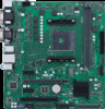
O_LPT_XSTB#_R O_LPT_XPD0_R O_LPT_XPD1_R O_LPT_XPD2_R O_LPT_XPD3_R O_LPT_XPD4_R O_LPT_XPD5_R O_LPT_XPD6_R O_LPT_XPD7_R O_LPT_ACK#_R O_LPT_BUSY_R O_LPT_PE_R O_LPT_SLCT_R O_LPT_XAFD#_R O_LPT_ERROR#_R O_LPT_XINIT#_R O_LPT_XSLIN#_R GND GND GND GND GND GND GND GND 15. LPT header The LPT (Line Printing Terminal) header supports devices such as a printer. LPT standardizes as IEEE 1284, which is the parallel port interface on IBM PC-compatible computers. PIN 1 GND SMBUS_CLK 16. System Management Bus header The System Management Bus (SMBus) connector allows you to connect a SMBus device. This connector is generally used for communication with the system and power management-related tasks. SMBUS PIN 1 SMBUS_DATA 17. Speaker header The 4-pin header is for the chassis-mounted system warning speaker. The speaker allows you to hear system beeps and warnings. +5V GND GND Speaker Out SPEAKER PIN 1 18. 10-1 pin System panel header This header supports several chassis-mounted functions. • System power LED (2-pin +PWR_LED-) F_PANEL +PWR_LED- PWR_BTN PWR_LED+ PWR_LEDPWR GND This 2-pin header is for the system power LED. Connect the chassis power LED cable to this header. The system power LED lights up when you turn on the system power, and blinks when the system is in sleep mode. PIN 1 HDD_LED+ HDD_LED- Ground HWRST# (NC) • Hard disk drive activity LED (2-pin +HDD_LED-) This 2-pin header is for the HDD Activity LED. Connect the HDD Activity LED cable to this header. The HDD LED lights up or flashes when data is read from or written to the HDD. +HDD_LED- RESET • Power button/Soft-off button (2-pin PWR_BTN) This header is for the system power button. • Reset button (2-pin RESET) This 2-pin header is for the chassis-mounted reset button for system reboot without turning off the system power. ASUS Pro A520M-C II 1-5
-
 1
1 -
2
-
3
-
4
-
5
-
6
-
7
-
 8
8 -
 9
9 -
 10
10 -
 11
11 -
 12
12 -
 13
13 -
 14
14 -
 15
15 -
 16
16 -
 17
17 -
 18
18 -
19
-
20
-
21
-
22
-
23
-
24
-
25
-
26
-
27
-
28
-
29
-
30
 |
 |
