Asus RAMPAGE III FORMULA Rampage III Formula User's manual - Page 35
Layout-Inhalt
 |
View all Asus RAMPAGE III FORMULA manuals
Add to My Manuals
Save this manual to your list of manuals |
Page 35 highlights
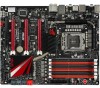
2.2.2 Layout-Inhalt Anschlüsse/Jumper/Schalter/Steckplätze 1. ATX-Netzanschlüsse (24-pol. EATXPWR, 8-pol. EATX12V, 4-pol. EZ_PLUG1-2) 2. Temperatursensorkabelanschlüsse (2-pol. OPT_TEMP1-3) 3. CPU-, Gehäuse- und optionale Lüfteranschlüsse (4-pol. CPU_FAN; 4-pol. PWR_FAN; 4-pol. CHA_FAN1-3; 4-pol. OPT_FAN1-3) 4. LGA1366 CPU-Sockel 5. DDR3 DIMM-Steckplätze 6. LN2 Mode-Jumper (3-pol. LN2) 7. Einschalttaste 8. Reset-Taste 9. Q Reset-Taste 10. QPI_LL (3-pol. QPI_LL_SW) 11. GO-Taste 12. Marvell® Serial ATA 6.0 Gb/s-Anschlüsse (7-pol. SATA_6G_1/2 [rot]) 13. ICH10R Serial ATA-Anschlüsse (7-pol. SATA 1-6 [grau]) 14. RTC RAM löschen (3-pol. CLRTC_SW) 15. BIOS-Schalter 16. Systemtafelanschluss (20-8 pol. PANEL) 17. USB-Anschlüsse (10-1 pol. USB78, USB910, USB11) 18. OC Station-Anschluss (8-pol. OC_STATION) 19. IEEE 1394a-Anschluss (10-1 pol. IE1394_2) 20. Digitaler Audioanschluss (4-1 pol. SPDIF_OUT) 21. Fronttafelaudioanschluss (10-1 pol. AAFP) Seite 2-45 2-43 2-42 2-9 2-14 2-31 2-48 2-48 2-50 2-31 2-49 2-39 2-38 2-30 2-49 2-46 2-40 2-40 2-41 2-43 2-44 Weitere Informationen zu den internen und Rücktafel -Anschlüssen finden Sie in Abschnitt 2.9 Anschlüsse. ROG Rampage III Formula 2-7
-
 1
1 -
2
-
3
-
4
-
5
-
6
-
7
-
8
-
9
-
10
-
11
-
12
-
13
-
14
-
15
-
16
-
17
-
18
-
19
-
20
-
21
-
22
-
23
-
24
-
25
-
26
-
27
-
28
-
29
-
 30
30 -
 31
31 -
 32
32 -
 33
33 -
 34
34 -
 35
35 -
 36
36 -
 37
37 -
 38
38 -
 39
39 -
 40
40 -
41
-
42
-
43
-
44
-
45
-
46
-
47
-
48
-
49
-
50
-
51
-
52
-
53
-
54
-
55
-
56
-
57
-
58
-
59
-
60
-
61
-
62
-
63
-
64
-
65
-
66
-
67
-
68
-
69
-
70
-
71
-
72
-
73
-
74
-
75
-
76
-
77
-
78
-
79
-
80
-
81
-
82
-
83
-
84
-
85
-
86
-
87
-
88
-
89
-
90
-
91
-
92
-
93
-
94
-
95
-
96
-
97
-
98
-
99
-
100
-
101
-
102
-
103
-
104
-
105
-
106
-
107
-
108
-
109
-
110
-
111
-
112
-
113
-
114
-
115
-
116
-
117
-
118
-
119
-
120
-
121
-
122
-
123
-
124
-
125
-
126
-
127
-
128
-
129
-
130
-
131
-
132
-
133
-
134
-
135
-
136
-
137
-
138
-
139
-
140
-
141
-
142
-
143
-
144
-
145
-
146
-
147
-
148
-
149
-
150
-
151
-
152
-
153
-
154
-
155
-
156
-
157
-
158
-
159
-
160
-
161
-
162
-
163
-
164
-
165
-
166
-
167
-
168
-
169
-
170
-
171
-
172
-
173
-
174
 |
 |
