Asus ThunderboltEX II DUAL User Guide - Page 6
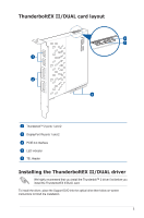
Installing the ThunderboltEX II/DUAL card - thunderboltex ii dual card
 |
View all Asus ThunderboltEX II DUAL manuals
Add to My Manuals
Save this manual to your list of manuals |
Page 6 highlights
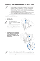
Installing the ThunderboltEX II/DUAL card • Before installing the ThunderboltEX II/DUAL card in your motherboard, ensure that you have an available PCIE 2.0 x16 slot connected to the platform controller hub (PCH). For more information on the correct PCIE 2.0 slot to use, refer to the section ThunderboltEX II/DUAL card recommended configuration of this user guide. • The following illustrations are for reference only. The motherboard layout may vary with models, but the installation steps remain the same. To install ThunderboltEX II/DUAL card: 1. Shut down your PC. 2. Open the chassis. Ensure that no cables or peripherals are blocking the PCIE 2.0 slot. 3. Align and insert the ThunderboltEX II/DUAL card into a PCIE 2.0 slot until it is securely seated in place. 4. For supported 8 Series motherboards, connect the ASUS TB_Header cable to the ThunderboltEX II/DUAL card (A) and to the TB_Header port on the motherboard (B). When the red LED on the ThunderboltEX II/DUAL card is on, it indicates that a cable is disconnected. Refer to the section ThunderboltEX II/DUAL card layout of this user guide for the location of the LED indicator. 6
-
 1
1 -
 2
2 -
 3
3 -
 4
4 -
 5
5 -
 6
6 -
 7
7 -
 8
8 -
 9
9 -
 10
10 -
 11
11 -
 12
12 -
13
-
14
-
15
-
16
 |
 |
