Asus Vintage-PH1 Vintage-PH1 User''s Manual for English E1943
Asus Vintage-PH1 Manual
 |
View all Asus Vintage-PH1 manuals
Add to My Manuals
Save this manual to your list of manuals |
Asus Vintage-PH1 manual content summary:
- Asus Vintage-PH1 | Vintage-PH1 User''s Manual for English E1943 - Page 1
Vintage-PH1 Barebone System - Asus Vintage-PH1 | Vintage-PH1 User''s Manual for English E1943 - Page 2
express written permission of ASUSTeK COMPUTER INC. ("ASUS"). Product warranty or service will not be extended if: (1) the ASUS HAS BEEN ADVISED OF THE POSSIBILITY OF SUCH DAMAGES ARISING FROM ANY DEFECT OR ERROR IN THIS MANUAL OR PRODUCT. SPECIFICATIONS AND INFORMATION CONTAINED IN THIS MANUAL - Asus Vintage-PH1 | Vintage-PH1 User''s Manual for English E1943 - Page 3
of contents Notices vii Safety information vii About this guide viii System package contents x Chapter 1: System CPU 2-5 2.4.1 Installling the CPU 2-5 2.4.2 Installling the CPU heatsink and fan 2-8 2.4.3 Uninstalling the CPU heatsink and fan 2-10 2.5 Installing a DIMM 2-12 2.5.1 Memory - Asus Vintage-PH1 | Vintage-PH1 User''s Manual for English E1943 - Page 4
Running the support CD 3-3 3.3.2 Utilities menu 3-4 3.2.3 ASUS Contact information 3-5 Chapter 4: Motherboard Info 4.1 Introduction 4-2 4.2 Motherboard layout 4-2 4.3 Jumpers 4-3 4.4 Connectors 4-6 Chapter 5: BIOS Information 5.1 Managing and updating your BIOS 5-2 5.1.1 Creating a bootable - Asus Vintage-PH1 | Vintage-PH1 User''s Manual for English E1943 - Page 5
Configuration 5-18 5.4.2 CPU Configuration 5-19 5.4.3 Chipset 5-20 5.4.4 Onboard Devices Configuration 5-22 5.4.5 PCI PnP 5-23 5.5 Power menu 5-25 5.5.1 Suspend Mode 5-25 5.5.2 Repost Video on S3 Resume 5-25 5.5.3 ACPI 2.0 Support 5-25 5.5.4 ACPI APIC Support 5-25 5.5.5 APM Configuration - Asus Vintage-PH1 | Vintage-PH1 User''s Manual for English E1943 - Page 6
. This equipment generates, uses and can radiate radio frequency energy and, if not installed and used in accordance with manufacturer's instructions, may cause harmful interference to radio communications. However, there is no guarantee that interference will not occur in a particular installation - Asus Vintage-PH1 | Vintage-PH1 User''s Manual for English E1943 - Page 7
connected. • If the power supply is broken, do not try to fix it by yourself. Contact a qualified service technician or your retailer on a stable surface. • If you encounter technical problems with the product, contact a qualified service technician or your retailer. Lithium-Ion Battery Warning C - Asus Vintage-PH1 | Vintage-PH1 User''s Manual for English E1943 - Page 8
About this guide Audience This guide provides general information and installation instructions about the ASUS Vintage-PH1 barebone system. This guide is intended for experienced users and integrators with hardware knowledge of personal computers. How this guide is organized This guide contains the - Asus Vintage-PH1 | Vintage-PH1 User''s Manual for English E1943 - Page 9
T : Instructions that you MUST follow to complete a task. N O T E : Tips and additional information to aid in completing a task. Where to find more information Refer to the following sources for additional information and for product and software updates. 1. ASUS Websites The ASUS websites worldwide - Asus Vintage-PH1 | Vintage-PH1 User''s Manual for English E1943 - Page 10
items. If any of the items is damaged or missing, contact your retailer immediately. Item description 1 . A S U S V i n t a g e - P H 1 b a r e b o n e s y s t e m with • ASUS motherboard • 300 W PFC/non-PFC power supply unit • ASUS chassis 2. Cable • AC power cable 3 . Support CD 4 . User guide x - Asus Vintage-PH1 | Vintage-PH1 User''s Manual for English E1943 - Page 11
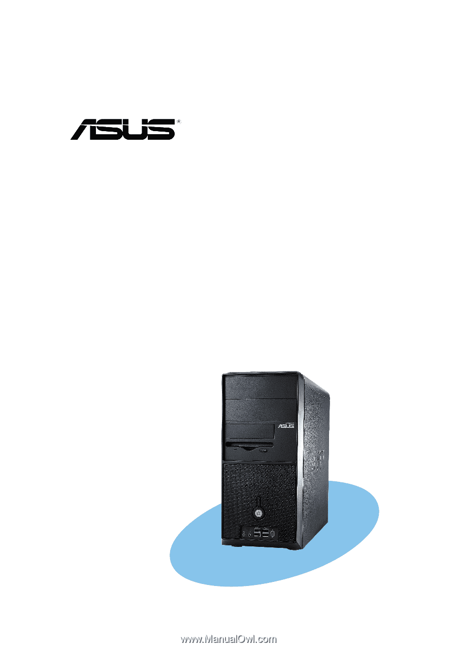
System introduction Chapter 1 This chapter gives a general description of the ASUS Vintage-PH1. The chapter lists the system features including introduction on the front and rear panel, and internal components. ASUS Vintage-PH1 - Asus Vintage-PH1 | Vintage-PH1 User''s Manual for English E1943 - Page 12
! The ASUS Vintage-PH1 is an all-in-one barebone system with a versatile home entertainment feature. The system comes in a stylish mini-tower casing and powered by the ASUS motherboard that supports the Intel® Pentium® 4 processor in the 775-land package with 800 MHz FSB and up to 2 GB system memory - Asus Vintage-PH1 | Vintage-PH1 User''s Manual for English E1943 - Page 13
disk. 4 . R e s e t b u t t o n. Press this button to reboot the system without turning off the power. 5 . P o w e r b u t t o n. Press this button to turn the system on. 6 . H e high-speed connectivity for audio/video devices, storage peripherals, PCs, or portable devices. ASUS Vintage-PH1 1-3 - Asus Vintage-PH1 | Vintage-PH1 User''s Manual for English E1943 - Page 14
1.3 Rear panel The system rear panel includes the power connector and several I/O ports that allow convenient connection of devices. 13 14 l p o r t . This port connects a mouse, modem, or other devices that conforms with serial specification. 4 . P a r a l l e l p o r t . This 25-pin port connects - Asus Vintage-PH1 | Vintage-PH1 User''s Manual for English E1943 - Page 15
o w e r s w i t c h . This switch allows you to turn ON or OFF the flow of power to the power supply unit. 1 4 . V o l t a g e s e l e c t o r . This switch ) through a network hub. 2 0 . E x p a n s i o n s l o t c o v e r s. Remove these cover when installing expansion cards. ASUS Vintage-PH1 1-5 - Asus Vintage-PH1 | Vintage-PH1 User''s Manual for English E1943 - Page 16
Voltage selector The PSU has a 115 V/230 V voltage selector switch located beside the power connector. Use this switch to select the appropriate system input voltage according to the voltage supply in your area. If the voltage supply in your area is 100-127 V, set the switch to 115 V. If the voltage - Asus Vintage-PH1 | Vintage-PH1 User''s Manual for English E1943 - Page 17
bay 3. Front panel cover 4. Hard disk drive metal tray 5. Chassis fan 6. ASUS motherboard 7. DIMM sockets 8. LGA775 socket with PnP cap 9. PCI Express™ x16 slot for discrete graphics card 10. PCI slots 11. Serial ATA connectors 12. Expansion card slots 13. Power supply unit ASUS Vintage-PH1 1-7 - Asus Vintage-PH1 | Vintage-PH1 User''s Manual for English E1943 - Page 18
1-8 Chapter 1: System introduction - Asus Vintage-PH1 | Vintage-PH1 User''s Manual for English E1943 - Page 19
Basic installation Chapter 2 This chapter provides step-by-step instructions on how to install components in the system. ASUS Vintage-PH1 - Asus Vintage-PH1 | Vintage-PH1 User''s Manual for English E1943 - Page 20
power supply case, before handling components to avoid damaging them due to static electricity. • Hold components by the edges to avoid touching the ICs on them. • Whenever you uninstall any component, place it on a grounded antistatic pad or in the bag that came with the component. The motherboard - Asus Vintage-PH1 | Vintage-PH1 User''s Manual for English E1943 - Page 21
rear until it disengages from the chassis. Remove only the left side plate. 3. Release the side lock tabs from the steel railing. Side lock tab ASUS Vintage-PH1 Steel railing 2-3 - Asus Vintage-PH1 | Vintage-PH1 User''s Manual for English E1943 - Page 22
4. Swing the left edge of the front panel outward. 5. Unhook the hinge-like tabs from the holes on the right side of the front panel to completely detach the front panel assembly from the chassis. Hinge-like tab 2-4 Chapter 2: Basic installation - Asus Vintage-PH1 | Vintage-PH1 User''s Manual for English E1943 - Page 23
, or misplacement/ loss/incorrect removal of the PnP cap. 2.4.1 Installling the CPU To install a CPU: 1. Locate the CPU socket on the motherboard. ® Socket 775 Before installing the CPU, make sure that the socket box is facing towards you and the load lever is on your left. ASUS Vintage-PH1 2-5 - Asus Vintage-PH1 | Vintage-PH1 User''s Manual for English E1943 - Page 24
. 4. Lift the load plate with your thumb and forefinger to a 100º angle (A), then push the PnP cap from the load plate window to remove (B). B A Load plate 5. Position the CPU over the socket, making sure that the gold triangle is on the bottom-left corner of the socket. The socket alignment key - Asus Vintage-PH1 | Vintage-PH1 User''s Manual for English E1943 - Page 25
2. Power up the system and enter the BIOS Setup (see Chapter 5: BIOS setup). Under the Advanced Menu, make sure that the item Hyper-Threading Technology is set to Enabled. The item appears only if you installed a CPU that supports Hyper-Threading Technology. 3. Reboot the computer. ASUS Vintage-PH1 - Asus Vintage-PH1 | Vintage-PH1 User''s Manual for English E1943 - Page 26
before you install the heatsink and fan assembly. To install the CPU heatsink and fan: 1. Place the heatsink on top of the installed CPU, making sure that the four fasteners match the holes on the motherboard. Fastener Motherboard hole Make sure each fastener is oriented as shown, with the narrow - Asus Vintage-PH1 | Vintage-PH1 User''s Manual for English E1943 - Page 27
place, connect the CPU fan cable to the connector on the motherboard labeled CPU_FAN1. CPU_FAN1 GND CPU FAN PWR CPU FAN IN CPU FAN PWM ® CPU fan connector Do not forget to connect the CPU fan connector! Hardware monitoring errors can occur if you fail to plug this connector. ASUS Vintage-PH1 2-9 - Asus Vintage-PH1 | Vintage-PH1 User''s Manual for English E1943 - Page 28
heatsink and fan To uninstall the CPU heatsink and fan: 1. Disconnect the CPU fan cable from the connector on the motherboard labeled CPU_FAN1. 2. Rotate each fastener counterclockwise. 3. Pull up two fasteners at a time in a diagonal sequence to disengage the heatsink B and fan assembly from - Asus Vintage-PH1 | Vintage-PH1 User''s Manual for English E1943 - Page 29
4. Remove the heatsink and fan assembly from the motherboard. 5. Rotate each fastener clockwise to reset the orientation. When reset, each fastener should be oriented as shown, with the narrow groove directed outward. ASUS Vintage-PH1 2-11 - Asus Vintage-PH1 | Vintage-PH1 User''s Manual for English E1943 - Page 30
For optimum compatibility, we recommend that you obtain memory modules from the same vendor. • Due to chipset resource allocation, the system may detect less than 2 GB system memory when you installed two 1 GB DDR memory. • This motherboard does not support memory modules made up of 128 Mb chips or - Asus Vintage-PH1 | Vintage-PH1 User''s Manual for English E1943 - Page 31
slots or the black slots as one pair of Dual-channel memory configuration. C - supports four modules inserted into the blue and black slots as two pairs of Dual-channel memory configuration. Visit the ASUS website (www.asus.com) for the latest DDR Qualified Vendors List. ASUS Vintage-PH1 2-13 - Asus Vintage-PH1 | Vintage-PH1 User''s Manual for English E1943 - Page 32
unplug the power supply before adding or removing DIMMs or other system components. Failure to do so may cause severe damage to both the motherboard and retaining clips outward to unlock the DIMM. 1 1 DDR DIMM notch Support the DIMM lightly with your fingers when pressing the retaining clips. The - Asus Vintage-PH1 | Vintage-PH1 User''s Manual for English E1943 - Page 33
by adjusting the software settings. 1. Turn on the system and change the necessary BIOS settings, if any. See Chapter 5 for information on BIOS setup. 2. Assign an IRQ to the card. Refer to the tables on the next page. 3. Install the software drivers for the expansion card. ASUS Vintage-PH1 2-15 - Asus Vintage-PH1 | Vintage-PH1 User''s Manual for English E1943 - Page 34
SATA Controller Onboard LAN A B C D E F -- -- shared - - shared -- -- -- shared - -- shared - -- -- -- shared - shared shared - - - shared - - - shared used G - used H - - - - shared - - - shared - - - - When using PCI cards on shared slots, ensure that the drivers support - Asus Vintage-PH1 | Vintage-PH1 User''s Manual for English E1943 - Page 35
card installed on the PCI Express x16 slot. 2.6.5 PCI Express x1 slot This motherboard supports PCI Express x1 network cards, SCSI cards and other cards that comply with the PCI Express specifications. The figure shows a network card installed on the PCI Express x1 slot. ASUS Vintage-PH1 2-17 - Asus Vintage-PH1 | Vintage-PH1 User''s Manual for English E1943 - Page 36
2.7 Installing an optical drive Follow these steps to install a CD-ROM drive. 1. Place the chassis upright. 2. Insert the CD-ROM drive into the upper 5.25-inch drive bay. 3. Carefully push the CD-ROM drive into the bay until its screw holes align with the holes on the bay as shown. 4. Secure the - Asus Vintage-PH1 | Vintage-PH1 User''s Manual for English E1943 - Page 37
5. Connect a power cable from the power supply to the power connector at the back of the CD- to the IDE Power cable connector on the motherboard. 9. Connect the other end of the audio cable to the black 4-pin connector labeled CD on the motherboard. Primary IDE connector ASUS Vintage-PH1 2-19 - Asus Vintage-PH1 | Vintage-PH1 User''s Manual for English E1943 - Page 38
2.8 Installing a hard disk drive The chassis has one 3.5-inch hard disk drive (HDD) bay right under the 5.25-inch bay. The following figures show the internal and external views of the HDD bay location. Internal view External view 5.25-inch Drive bay 3.5-inch drive bay Follow these steps to - Asus Vintage-PH1 | Vintage-PH1 User''s Manual for English E1943 - Page 39
5. Connect a power cable from the power supply to the power connector at the back of the HDD. interface. Red stripe to Pin 1 IDE ribbon cable Power cable 7. Connect the other end of the IDE ribbon cable to the primary IDE connector on the motherboard. Primary IDE connector ASUS Vintage-PH1 2-21 - Asus Vintage-PH1 | Vintage-PH1 User''s Manual for English E1943 - Page 40
Vintage-PH1 system comes with one 3.25-inch drive bay for a floppy disk drive. To install a floppy disk drive: 1. Remove the front panel cover. For instructions disk drive connector on the motherboard. 6. Connect a power cable from the power supply unit to the power connector at the back of the - Asus Vintage-PH1 | Vintage-PH1 User''s Manual for English E1943 - Page 41
+ IDE_LED- Ground Reset System panel connector IDELED RESET * Requires an ATX power supply. Connect the r e s e t b u t t o n , p o w e r s w i t c h, p o w e r L E D , and H D D L E D cables to their respective leads in the system panel connector on the motherboard. ASUS Vintage-PH1 2-23 - Asus Vintage-PH1 | Vintage-PH1 User''s Manual for English E1943 - Page 42
2.11 Replacing the side plate and front cover After you have installed all the internal components and you have connected all the necessary cables, you are now ready to put the system back together. 1. Hook the hinge-like tabs to the holes on the right side of the front panel to attach the front - Asus Vintage-PH1 | Vintage-PH1 User''s Manual for English E1943 - Page 43
hole on the chassis to indicate that the side plate is in place. 6. Lock the side plate with the screws on the rear panel. Screw ASUS Vintage-PH1 2-25 - Asus Vintage-PH1 | Vintage-PH1 User''s Manual for English E1943 - Page 44
2.13 Connecting external devices The figure below shows the specific connectors and devices that you can connect to the rear panel ports. PS/2 KB Serial VGA RJ-45 Center/ Subwoofer Side Speaker AC PS/2 Mouse - Asus Vintage-PH1 | Vintage-PH1 User''s Manual for English E1943 - Page 45
Chapter 3 This chapter helps you power up the system and install drivers and utilities from the support CD. ASUS Vintage-PH1 Starting up - Asus Vintage-PH1 | Vintage-PH1 User''s Manual for English E1943 - Page 46
3.1 Installing an operating system The barebone system supports Windows® 2000/XP operating systems (OS). Always install the latest OS version and corresponding updates so you can maximize the features of your hardware. Because motherboard settings and hardware options vary, use the setup procedures - Asus Vintage-PH1 | Vintage-PH1 User''s Manual for English E1943 - Page 47
to run the CD. QFE Update Installs the Quick Fix Engineering (QFE) driver updates. Intel Chipset Inf Update Program This item installs the Intel® Chipset INF Update Program. This driver enables Plug-n-Play INF support for the Intel® chipset components on the motherboard. When installed to the target - Asus Vintage-PH1 | Vintage-PH1 User''s Manual for English E1943 - Page 48
Driver. USB 2.0 Driver Installs the USB 2.0 driver. 3.3.2 Utilities menu The Utilities menu shows the applications and other software that the motherboard supports. ASUS PC Probe This smart utility monitors the fan speed, CPU temperature, and system voltages, and alerts you of any detected problems - Asus Vintage-PH1 | Vintage-PH1 User''s Manual for English E1943 - Page 49
ASUS Update The ASUS Update utility allows you to update the motherboard BIOS in a Windows® environment. This utility requires an Internet connection either through a network or an Internet Service Provider (ISP). Microsoft DirectX Installs the Microsoft® DirectX 9.0c driver. Anti-virus application - Asus Vintage-PH1 | Vintage-PH1 User''s Manual for English E1943 - Page 50
3-6 Chapter 3: Starting up - Asus Vintage-PH1 | Vintage-PH1 User''s Manual for English E1943 - Page 51
Motherboard info Chapter 4 This chapter gives information about the motherboard that comes with the system. This chapter includes the motherboard layout, jumper settings, and connector locations. ASUS Vintage-PH1 - Asus Vintage-PH1 | Vintage-PH1 User''s Manual for English E1943 - Page 52
Vintage-PH1 barebone system comes with an ASUS motherboard. This chapter provides technical information about the motherboard for future upgrades or system reconfiguration. 4.2 Motherboard IDE_LED+ IDE_LED- Ground Reset IDELED RESET * Requires an ATX power supply. 4-2 Chapter 4: Motherboard info - Asus Vintage-PH1 | Vintage-PH1 User''s Manual for English E1943 - Page 53
key during the boot process and enter BIOS setup to re-enter data. ® Clear RTC RAM CLRTC1 12 23 Normal (Default) Clear CMOS Except when clearing the RTC RAM, never remove the cap on CLRTC jumper default position. Removing the cap will cause system boot failure. ASUS Vintage-PH1 4-3 - Asus Vintage-PH1 | Vintage-PH1 User''s Manual for English E1943 - Page 54
sleep modes (no power to CPU, DRAM in slow refresh, power supply in reduced power mode). USBPW12 USBPW34 power supply that can supply at least 1A on the +5VSB lead, and a corresponding setting in the BIOS. KBPWR1 12 23 +5V +5VSB (Default) ® Keyboard power setting 4-4 Chapter 4: Motherboard - Asus Vintage-PH1 | Vintage-PH1 User''s Manual for English E1943 - Page 55
allows you to connect either a 3-pin or a 4-pin fan cable plug to the CPU fan connector (CPU_FAN1). Set this jumper to pins 1-2 if you are using a 4-pin fan cable plug, or to pins 2-3 if you are using a 3-pin plug. FANPWR1 12 23 PWM (Default) DC mode ® FAN power setting ASUS Vintage-PH1 4-5 - Asus Vintage-PH1 | Vintage-PH1 User''s Manual for English E1943 - Page 56
Ultra DMA 100/66 signal cable. The Ultra DMA 100/66 signal cable has three connectors: a blue connector for the primary IDE connector on the motherboard, a black connector for an Ultra DMA 100/66 IDE slave device (optical drive/hard disk drive), and a gray connector for an Ultra DMA 100/66 - Asus Vintage-PH1 | Vintage-PH1 User''s Manual for English E1943 - Page 57
signal cables for Serial ATA hard disk drives. ® SATA connectors SATA4 GND RSATA_TXP4 RSATA_TXN4 GND RSATA_RXP4 RSATA_RXN4 GND SATA3 on Serial ATA • You must install Windows® 2000 Service Pack 4 or the Windows® XP Service Pack1 before using Serial ATA hard disk Data Disk ASUS Vintage-PH1 4-7 - Asus Vintage-PH1 | Vintage-PH1 User''s Manual for English E1943 - Page 58
CPU and Chassis Fan connectors (4-pin CPU_FAN1, 3-pin CHA_FAN1) The fan connectors support cooling fans of 350 mA~740 mA (8.88 W max.) or a total of 1 A~2.22 A (26.64 W max.) at +12V. Connect the fan cables to the fan connectors on the motherboard may damage the motherboard components. These are - Asus Vintage-PH1 | Vintage-PH1 User''s Manual for English E1943 - Page 59
at the back of the system chassis. These USB connectors comply with USB 2.0 specification that supports up to 480 Mbps connection speed. USB+5V USB_P8USB_P8+ GND NC USB+5V to the USB connectors. Doing so will damage the motherboard! The USB module is purchased separately. ASUS Vintage-PH1 4-9 - Asus Vintage-PH1 | Vintage-PH1 User''s Manual for English E1943 - Page 60
requirements • Do not forget to connect the 4-pin ATX +12 V power plug; otherwise, the system will not boot up. • To power the motherboard, it is recommended that you use an ATX 12 V Specification 2.0 power supply unit (PSU) with a minimum 350 W power rating. This PSU type has a 24-pin and 4-pin ATX - Asus Vintage-PH1 | Vintage-PH1 User''s Manual for English E1943 - Page 61
10-1 pin AAFP1) This connector is for a chassis-mounted front panel audio I/O module that supports either HD Audio or legacy AC'97 audio standard. AAFP1 Azalia Legacy AC'97 compliant definition this connector to use the high-definition audio features of the motherboard. ASUS Vintage-PH1 4-11 - Asus Vintage-PH1 | Vintage-PH1 User''s Manual for English E1943 - Page 62
the jumper caps only when you intend to use the chassis intrusion detection feature. CHASSIS1 +5VSB_MB Chassis Signal GND ® Chassis intrusion connector (Default) 4-12 Chapter 4: Motherboard info - Asus Vintage-PH1 | Vintage-PH1 User''s Manual for English E1943 - Page 63
PLED1) This 3-1 pin connector is for the system power LED. Connect the 3-pin power LED cable from the system chassis to this connector. The LED lights up when you turn on the system power, and blinks when the system is in sleep mode. ® PLED setting PLED+ NC PLED- PLED1 1 ASUS Vintage-PH1 4-13 - Asus Vintage-PH1 | Vintage-PH1 User''s Manual for English E1943 - Page 64
14. System panel connector (10-1 pin F_PANEL1) This connector supports several chassis-mounted functions. ® System panel connector IDE_LED+ IDE_LED- Ground Reset PLED+ PLEDPWR GND PLED PWRSW F_PANEL1 IDELED RESET * Requires an ATX power supply. The sytem panel connector is color-coded for easy - Asus Vintage-PH1 | Vintage-PH1 User''s Manual for English E1943 - Page 65
Chapter 5 This chapter tells how to change system settings through the BIOS Setup menus and describes the BIOS parameters. BIOS setup ASUS Vintage-PH1 1 - Asus Vintage-PH1 | Vintage-PH1 User''s Manual for English E1943 - Page 66
motherboard BIOS using the ASUS Update or AFUDOS utilities. 5.1.1 Creating a bootable floppy disk 1. Do either one of the following to create a bootable floppy disk. DOS environment a. Insert a 1.44MB floppy disk into the drive. b. At the DOS prompt, type format A:/S then press . Windows® XP - Asus Vintage-PH1 | Vintage-PH1 User''s Manual for English E1943 - Page 67
by pressing + during the Power-On Self Tests (POST). To update the BIOS using EZ Flash: 1. Visit the ASUS website (www.asus.com) to download the latest BIOS file for the motherboard and rename the same to P H 1 6 T . R O M. 2. Save the BIOS file to a floppy disk, then restart the system - Asus Vintage-PH1 | Vintage-PH1 User''s Manual for English E1943 - Page 68
least 600 KB free space to save the file. • The succeeding BIOS screens are for reference only. The actual BIOS screen displays may not be exactly the same as shown. 1. Copy the AFUDOS utility (afudos.exe) from the motherboard support CD to the bootable floppy disk you created earlier. 2. Boot the - Asus Vintage-PH1 | Vintage-PH1 User''s Manual for English E1943 - Page 69
off power during flash BIOS Reading file ..... done Reading flash .... done Search bootblock version Advance Check........ Erasing flash .... done Writing flash .... 0x0008CC00 (9%) Do not shut down or reset the system while updating the BIOS to prevent system boot failure! ASUS Vintage-PH1 5-5 - Asus Vintage-PH1 | Vintage-PH1 User''s Manual for English E1943 - Page 70
the BIOS update process is completed. Reboot the system from the hard disk drive. A:\>afudos /iPH16T.ROM AMI Firmware Update Utility - Version 1.19(ASUS V2.07(03.11.24BB)) Copyright (C) 2003 American Megatrends, Inc. All rights reserved. WARNING!! Do not turn off power during flash BIOS Reading - Asus Vintage-PH1 | Vintage-PH1 User''s Manual for English E1943 - Page 71
drive for the original or updated BIOS file. The utility then updates the corrupted BIOS file. Bad BIOS checksum. Starting BIOS recovery... Checking for floppy... Floppy not found! Checking for CD-ROM... CD-ROM found! Reading file "PH16T.ROM". Completed. Start flashing... ASUS Vintage-PH1 5-7 - Asus Vintage-PH1 | Vintage-PH1 User''s Manual for English E1943 - Page 72
be the latest BIOS version for this motherboard. Visit the ASUS website (www.asus.com) to download the latest BIOS file. 5.1.5 ASUS Update utility The ASUS Update is a utility that allows you to manage, save, and update the motherboard BIOS in Windows® environment. The ASUS Update utility allows you - Asus Vintage-PH1 | Vintage-PH1 User''s Manual for English E1943 - Page 73
d a t e. The ASUS Update main window appears. 2. Select U p d a t e B I O S f r o m 3. Select the ASUS FTP site t h e I n t e r n e t option from the nearest you to avoid network drop-down menu, then click traffic, or click A u t o S e l e c t. N e x t. Click N e x t. ASUS Vintage-PH1 5-9 - Asus Vintage-PH1 | Vintage-PH1 User''s Manual for English E1943 - Page 74
to download. Click Next. 5. Follow the screen instructions to complete the update process. The ASUS Update utility is capable of updating itself through the Internet. Always update the utility to avail all its features. Updating the BIOS through a BIOS file To update the BIOS through a BIOS file - Asus Vintage-PH1 | Vintage-PH1 User''s Manual for English E1943 - Page 75
the Exit Menu. See section "5.7 Exit Menu." • The BIOS setup screens shown in this section are for reference purposes only, and may not exactly match what you see on your screen. • Visit the ASUS website (www.asus.com) to download the latest BIOS file for this motherboard. ASUS Vintage-PH1 5-11 - Asus Vintage-PH1 | Vintage-PH1 User''s Manual for English E1943 - Page 76
changing the basic system configuration For changing the advanced system settings For changing the advanced power management (APM) configuration For changing the system boot configuration For selecting the exit options navigation keys differ from one screen to another. 5-12 Chapter 5: BIOS setup - Asus Vintage-PH1 | Vintage-PH1 User''s Manual for English E1943 - Page 77
item on the menu bar displays the specific items for that menu. For example, selecting M a i n shows the Main menu items. The other items (Advanced, Power, Boot, and Exit) on the menu of the menu screen is a brief description of the selected item. Pop-up window Scroll bar ASUS Vintage-PH1 5-13 - Asus Vintage-PH1 | Vintage-PH1 User''s Manual for English E1943 - Page 78
screen appears, giving you an overview of the basic system information. Refer to section "5.2.1 BIOS menu screen" for information on the menu screen items and how to navigate through them. , 5.25 in.] [1.2M , 5.25 in.] [720K , 3.5 in.] [1.44M, 3.5 in.] [2.88M, 3.5 in.] 5-14 Chapter 5: BIOS setup - Asus Vintage-PH1 | Vintage-PH1 User''s Manual for English E1943 - Page 79
the BIOS automatically device type. Select CDROM if you are specifically configuring a CD-ROM drive. Select supports multi-sector transfer feature. When set to [Disabled], the data transfer from and to the device occurs one sector at a time. Configuration options: [Disabled] [Auto] ASUS Vintage-PH1 - Asus Vintage-PH1 | Vintage-PH1 User''s Manual for English E1943 - Page 80
-bit Support On IDE Detect Time Out (Sec) [Enhanced Mode] [SATA mode] [35] Set to [Compatible Mode] when Legacy OS (i.e. WIN ME, 98, NT4.0, MS DOS is used. Set to [Enhanced Mode when Native OS) i.e. WIN 2000, WIN XP Windows® 2000/XP. Configuration options: [Disabled] [Compatible Mode] [Enhanced - Asus Vintage-PH1 | Vintage-PH1 User''s Manual for English E1943 - Page 81
/04 Processor Type Speed Count : Genuine Intel(R) CPU 3.20GHz : 3200 MHz : 1 System Memory Size : 248MB AMI BIOS Displays the auto-detected BIOS information. Processor Displays the auto-detected CPU specification. System Memory Displays the auto-detected system memory. ASUS Vintage-PH1 5-17 - Asus Vintage-PH1 | Vintage-PH1 User''s Manual for English E1943 - Page 82
can cause the system to malfunction. USB Configuration CPU Configuration Chipset Onboard Devices Configuration PCI PnP Configure the USB support. 5.4.1 USB Configuration The items in this menu disable the USB function. Configuration options: [Disabled] [Enabled] 5-18 Chapter 5: BIOS setup - Asus Vintage-PH1 | Vintage-PH1 User''s Manual for English E1943 - Page 83
auto-detected by BIOS. Use the < + > or < - > keys to adjust the values. VID CMOS Setting [ 62] Allows you to set the VID CMOS setting at which the processor is to run. The default value of this item is auto-detected by BIOS. Use the < + > or < - > keys to adjust the values. ASUS Vintage-PH1 5-19 - Asus Vintage-PH1 | Vintage-PH1 User''s Manual for English E1943 - Page 84
BIOS will automatically check the CPU's capability to enable the C1E support. In C1E mode, the CPU power consumption is lower when idle. Configuration options: [Auto] [Disabled] CPU VGA] Internal Graphics Mode Select [Enabled, 8M] Graphics Memory Type [Auto] Enable or disable DRAM timing. PCI- - Asus Vintage-PH1 | Vintage-PH1 User''s Manual for English E1943 - Page 85
Memory Type [Auto] Disables or sets the graphics memory type. Configuration options: [Auto] [DVMT] [FIX] [DVMT+FIX] VC1 for Azalia & Root Ports [Disabled] Enables or disables the VC1 for the Azalia audio ports and other root ports. Configuration options: [Disabled] [Enabled] ASUS Vintage-PH1 - Asus Vintage-PH1 | Vintage-PH1 User''s Manual for English E1943 - Page 86
] [3E8/IRQ4] [2E8/IRQ3] Parallel Port Address [378] Allows you to select the Parallel Port base addresses. Configuration options: [Disabled] [378] [278] [3BC] 5-22 Chapter 5: BIOS setup - Asus Vintage-PH1 | Vintage-PH1 User''s Manual for English E1943 - Page 87
includes setting IRQ and DMA channel resources for either PCI/PnP or legacy ISA devices, and setting the memory size block for legacy ISA devices. Take caution when changing the settings of the PCI PnP menu . Reserved: Specified IRQ is reserved for use by Legacy ISA devices. ASUS Vintage-PH1 5-23 - Asus Vintage-PH1 | Vintage-PH1 User''s Manual for English E1943 - Page 88
options: [Disabled] [Enabled] PCI IDE BusMaster [Enabled] Allows BIOS to use PCI bus mastering when reading/writing to IDE devices. ] [PCI Slot6] IRQ-xx assigned to [PCI Device] When set to [PCI Device], the specific IRQ is free for use of PCI/PnP devices. When set to [Reserved], the IRQ is - Asus Vintage-PH1 | Vintage-PH1 User''s Manual for English E1943 - Page 89
you to enable or disable the Advanced Configuration and Power Interface (ACPI) support in the Advanced Programmable Interrupt Controller (APIC). When set to Enabled, the ACPI APIC table pointer is included in the RSDT pointer list. Configuration options: [Disabled] [Enabled] ASUS Vintage-PH1 5-25 - Asus Vintage-PH1 | Vintage-PH1 User''s Manual for English E1943 - Page 90
. Power On By PCI Devices [Disabled] When set to [Enabled], this parameter allows you to turn on the system through a PCI LAN or modem card. This feature requires an ATX power supply that provides at least 1A on the +5VSB lead. Configuration options: [Disabled] [Enabled] 5-26 Chapter 5: BIOS setup - Asus Vintage-PH1 | Vintage-PH1 User''s Manual for English E1943 - Page 91
[ 1.320V] [ 3.345V] [ 5.094V] [11.880V] CPU Temperature [xxxºC/xxxºF] MB Temperature [xxxºC/xxxºF] The onboard hardware monitor automatically detects and displays the motherboard and CPU temperatures. Select Disabled if you do not wish to display the detected temperatures. ASUS Vintage-PH1 5-27 - Asus Vintage-PH1 | Vintage-PH1 User''s Manual for English E1943 - Page 92
motherboard, the field shows N/A. CPU Q-Fan Control [Enabled] Allows you to enable or disable the ASUS options: [Disabled] [Enabled] CPU Fan Ratio [Auto] Allows you to select the appropriate CPU fan speed ratio for the system connected to the chassis, the specific field shows N/A. VCORE Voltage, - Asus Vintage-PH1 | Vintage-PH1 User''s Manual for English E1943 - Page 93
. The number of device items that appears on the screen depends on the number of devices installed in the system. Configuration options: [xxxxx Drive] [Disabled] ASUS Vintage-PH1 5-29 - Asus Vintage-PH1 | Vintage-PH1 User''s Manual for English E1943 - Page 94
use the ASUS MyLogo™ feature. Add On ROM Display Mode [Force BIOS] Sets the display mode for option ROM. Configuration options: [Force BIOS] [Keep Current] Bootup Num-Lock [On] Allows you to select the power-on state for the NumLock. Configuration options: [Off] [On] PS/2 Mouse Support [Auto] Allows - Asus Vintage-PH1 | Vintage-PH1 User''s Manual for English E1943 - Page 95
same steps as in setting a user password. To clear the supervisor password, select the Change Supervisor Password then press . The message "Password Uninstalled" appears. ASUS Vintage-PH1 5-31 - Asus Vintage-PH1 | Vintage-PH1 User''s Manual for English E1943 - Page 96
If you forget your BIOS password, you clear it by erasing the CMOS Real Time Clock (RTC) RAM. See section "4.3 Jumpers" for information on how to type a password composed of at least six letters and/or numbers, then press . 3. Confirm the password when prompted. 5-32 Chapter 5: BIOS setup - Asus Vintage-PH1 | Vintage-PH1 User''s Manual for English E1943 - Page 97
and save or discard your changes to the BIOS items. Exit Options Exit & Save Changes Exit & Discard Changes Discard Changes Load Setup Defaults Pressing does not immediately exit this menu. Select one of the options from this menu or from the legend bar to exit. ASUS Vintage-PH1 5-33 - Asus Vintage-PH1 | Vintage-PH1 User''s Manual for English E1943 - Page 98
even when the PC is turned off. When you select this option, a confirmation window appears. Select O k to save changes and exit. If you attempt to exit to fields other than System Date, System Time, and Password, the BIOS asks for a confirmation before exiting. Discard Changes This option allows you
-
 1
1 -
 2
2 -
 3
3 -
 4
4 -
 5
5 -
 6
6 -
 7
7 -
8
-
9
-
10
-
11
-
12
-
13
-
14
-
15
-
16
-
17
-
18
-
19
-
20
-
21
-
22
-
23
-
24
-
25
-
26
-
27
-
28
-
29
-
30
-
31
-
32
-
33
-
34
-
35
-
36
-
37
-
38
-
39
-
40
-
41
-
42
-
43
-
44
-
45
-
46
-
47
-
48
-
49
-
50
-
51
-
52
-
53
-
54
-
55
-
56
-
57
-
58
-
59
-
60
-
61
-
62
-
63
-
64
-
65
-
66
-
67
-
68
-
69
-
70
-
71
-
72
-
73
-
74
-
75
-
76
-
77
-
78
-
79
-
80
-
81
-
82
-
83
-
84
-
85
-
86
-
87
-
88
-
89
-
90
-
91
-
92
-
93
-
94
-
95
-
96
-
97
-
98
 |
 |
Vintage-PH1
Barebone System