Asus X99-A/USB 3.1TRANSFER EXPRESS User Guide
Asus X99-A/USB 3.1TRANSFER EXPRESS Manual
 |
View all Asus X99-A/USB 3.1TRANSFER EXPRESS manuals
Add to My Manuals
Save this manual to your list of manuals |
Asus X99-A/USB 3.1TRANSFER EXPRESS manual content summary:
- Asus X99-A/USB 3.1TRANSFER EXPRESS | User Guide - Page 1
Motherboard X99-A/USB 3.1 - Asus X99-A/USB 3.1TRANSFER EXPRESS | User Guide - Page 2
ASUS"). Product warranty or service will not be extended or missing. ASUS PROVIDES THIS MANUAL "AS IS" WITHOUT WARRANTY OF (1) for free by downloading it from http://support.asus.com/download or (2) for the cost If however you encounter any problems in obtaining the full corresponding source - Asus X99-A/USB 3.1TRANSFER EXPRESS | User Guide - Page 3
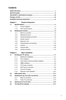
Contents Safety information...v About this guide...vi X99-A/USB 3.1 specifications summary viii Package contents...xiv Installation tools and components xv Chapter 1: Product Introduction 1.1 Special features 1-1 1.1.1 Product highlights 1-1 1.1.2 Other special features 1-2 1.2 - Asus X99-A/USB 3.1TRANSFER EXPRESS | User Guide - Page 4
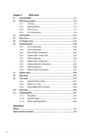
Chapter 3: BIOS setup 3.1 Knowing BIOS 3-1 3.2 BIOS setup program 3-2 3.2.1 EZ Mode 3-3 3.2.2 Advanced Mode 3-4 3.2.3 QFan Control 3-7 3.2.4 EZ Tuning Wizard 3-9 3.3 My Favorites 3-11 3.4 Main menu 3-13 3.5 Ai Tweaker menu 3-15 3.6 Advanced menu 3-32 3.6.1 CPU Configuration 3- - Asus X99-A/USB 3.1TRANSFER EXPRESS | User Guide - Page 5
Contact a qualified service technician or your retailer. Operation safety • Before installing the motherboard and adding devices on it, carefully read all the manuals that came with . • If you encounter technical problems with the product, contact a qualified service technician or your retailer. v - Asus X99-A/USB 3.1TRANSFER EXPRESS | User Guide - Page 6
when installing and configuring the motherboard. How this guide is organized This guide contains the following parts: 1. Chapter 1: Product introduction This chapter describes the features of the motherboard and the new technology it supports. It includes description of the switches, jumpers, and - Asus X99-A/USB 3.1TRANSFER EXPRESS | User Guide - Page 7
note of the following symbols used throughout this manual. DANGER/WARNING: Information to prevent injury to yourself when trying to complete a task. CAUTION: Information to prevent damage to the components when trying to complete a task IMPORTANT: Instructions that you MUST follow to complete a task - Asus X99-A/USB 3.1TRANSFER EXPRESS | User Guide - Page 8
The PCIe x16_4 slot shares bandwidth with M.2 x4. When the M.2 socket is occupied, the PCIe x16_4 will be disabled. ** The PCIe x16_3 slot supports GEN3 discrete cards and x8 devices only. ***The PCIe x16_2, PCIe x1_1, and USB3_E56 connectors share the same bandwidth. By default, the PCIe x16_2 slot - Asus X99-A/USB 3.1TRANSFER EXPRESS | User Guide - Page 9
chipset behavior, the SATA6G_78 and SATA6G_910 ports (black) do not support Intel® Rapid Storage Technology including RAID configuration. ** These functions work -out at back) and 104 dB SNR recording input (Line-in) support - Absolute Pitch 192 khz/24 bit True BD Lossless Sound - BD audio layer content - Asus X99-A/USB 3.1TRANSFER EXPRESS | User Guide - Page 10
X99-A/USB 3.1 specifications summary ASUS Exclusive Features Flagship Performance 5-Way Optimization by Dual Intelligent Processors 5 - Whole system optimization with a single click! 5-Way Optimization tuning key perfectly consolidates TPU, EPU, DIGI+ Power Control, Fan Xpert 3, and Turbo APP - Asus X99-A/USB 3.1TRANSFER EXPRESS | User Guide - Page 11
Turbo LAN - Experience smooth online gaming with lower pings and less lag Crystal Sound 2 - Feel the sound power with different usage scenarios Steam support - Compatible with the most fun gaming platform under Windows® system ASUS EZ DIY Push Notice - Monitor your PC status with smart devices in - Asus X99-A/USB 3.1TRANSFER EXPRESS | User Guide - Page 12
Flashback button 1 x Optical S/PDIF Out port 1 x Intel® LAN (RJ45) port 2 x USB 3.1/3.0/2.0 ports (teal blue) 4 x USB 3.0/2.0 ports (blue) 4 x USB 2.0/1.1 ports (bottom port supports USB BIOS Flashback) 1 x Keyboard/Mouse combo connector 8-channel Audio I/O ports 2 x 19-pin USB 3.0/2.0 connectors - Asus X99-A/USB 3.1TRANSFER EXPRESS | User Guide - Page 13
(PWM Mode) coolers control 1 x Front panel audio connector(AAFP) 1 x S/PDIF Out header 1 x 5-pin Thunderbolt header for ASUS ThunderboltEX series support 1 x TPM connector 1 x Serial port (COM) header 1 x 24-pin EATX Power connector 1 x 8-pin EATX 12V Power connector 1 x System Panel (Q-Connector - Asus X99-A/USB 3.1TRANSFER EXPRESS | User Guide - Page 14
ASUS X99-A/USB 3.1 motherboard 4 x Serial ATA 6 Gb/s cables 1 x ASUS Q-Shield 1 x ASUS SLI™ bridge connector 1 x 2-in-1 ASUS Q-Connector kit User Manual Support DVD Technical documentations • If any of the above items is damaged or missing, contact your retailer. • The illustrated items above - Asus X99-A/USB 3.1TRANSFER EXPRESS | User Guide - Page 15
Installation tools and components Intel® LGA2011-v3 CPU Intel® LGA2011-v3 compatible CPU Fan PC chassis SATA hard disk drive Philips (cross) screwdriver Power supply unit 1 bag of screws DIMM SATA optical disc drive (optional) Graphics card The tools and components in the table above are - Asus X99-A/USB 3.1TRANSFER EXPRESS | User Guide - Page 16
xvi - Asus X99-A/USB 3.1TRANSFER EXPRESS | User Guide - Page 17
of the SSDs. It also features backward compatibility with up to two SATA drives of the same speed. Quad-Channel DDR4 3333 MHz Support The motherboard supports the quad-channel DDR4 memory that features data transfer rates of DDR4 3333 MHz to boost the system's performance, and to meet the higher - Asus X99-A/USB 3.1TRANSFER EXPRESS | User Guide - Page 18
Complete USB 3.1 integration This motherboard has the latest USB 3.1 connectivity built in with dual Type-A ports for the very fastest USB data transfers - that's up to 10 Gb/s, or twice as fast as USB 3.0. The next-generation standard is completely backward-compatible with your existing USB devices - Asus X99-A/USB 3.1TRANSFER EXPRESS | User Guide - Page 19
1.2 Motherboard overview 1.2.1 Before you proceed Take note of the following precautions before you install motherboard components or change any motherboard settings. • Unplug the power cord from the wall socket before touching any component. • Before handling components, use a grounded wrist strap - Asus X99-A/USB 3.1TRANSFER EXPRESS | User Guide - Page 20
1.2.2 Motherboard layout Chapter 1 Refer to 1.2.9 Internal connectors and 2.3.1 Rear I/O connection for more information about rear panel connectors and internal connectors. 1-4 Chapter 1: Product introduction - Asus X99-A/USB 3.1TRANSFER EXPRESS | User Guide - Page 21
Layout contents Connectors/Jumpers/Buttons and switches/Slots 1. DDR4 DIMM slots 2. CPU, CPU optional, extension, and chassis fan connectors (4-pin CPU_FAN, 4-pin CPU_OPT, 5-pin EXT_FAN, 4-pin CHA_FAN1-4 ) 3. LGA2011-v3 CPU socket 4. ATX power connectors (24-pin EATXPWR; 8-pin EATX12V) 5. MemOK! - Asus X99-A/USB 3.1TRANSFER EXPRESS | User Guide - Page 22
1.2.3 Central Processing Unit (CPU) The motherboard comes with a surface mount LGA2011-v3 socket designed for Intel® Core™ i7 processors. • Ensure that all power cables are unplugged before installing the CPU. • Upon purchase of the motherboard, ensure that the PnP cap is on the socket and the - Asus X99-A/USB 3.1TRANSFER EXPRESS | User Guide - Page 23
1.2.4 System memory The motherboard comes with eight DDR 4 (Double Data Rate 4) Quad Inline Memory Modules (DIMM) slots. A DDR4 module is notched differently from a DDR, DDR2, or DDR3 module. DO NOT install a DDR, DDR2, or DDR3 memory module to the DDR4 slot. Recommended memory configurations - Asus X99-A/USB 3.1TRANSFER EXPRESS | User Guide - Page 24
at the vendor-marked or at a higher frequency, refer to section 3.5 Ai Tweaker menu for manual memory frequency adjustment. • For system stability, use a more efficient memory cooling system to support a full memory load (8 DIMMs) or overclocking condition. • Always install the DIMMS with the same - Asus X99-A/USB 3.1TRANSFER EXPRESS | User Guide - Page 25
A_DATA AX4U3333W4G16 16GB(4GB*4) SS SK hynix Chip NO. H5AN4G8NMFR Timing 16-16-16-36 16-16-16-36 Voltage 1.35V 1.35V DIMM socket support (Optional) 24 8 •• •• DDR4 3300 (O.C.) MHz capability (U-DIMM) Vendors Part No. Size SS/ Chip Brand DS G.SKILL F4-3300C16Q-16GRK 16GB(4GB*4) SS SK hynix - Asus X99-A/USB 3.1TRANSFER EXPRESS | User Guide - Page 26
/ Chip Chip NO. Timing Voltage DIMM socket DS Brand support (Optional) 248 A_DATA AX4U2800W8G17-DRZ 8GB DS SK hynix 32GB(8GB*4) CMK32GX4M4A2666C16R 32GB (4x 8GB) SS/ Chip Chip Timing DS Brand NO. Voltage DIMM socket support (Optional) 24 8 SS - - 14-16-16-35 1.2V • • DS - - 14- - Asus X99-A/USB 3.1TRANSFER EXPRESS | User Guide - Page 27
/ Chip DS Brand Chip NO. Timing Voltage DIMM socket support (Optional) 24 8 SS SK hynix H5AN4G8NMFR 16-16- 15-15-15-35 - 15-15-15-35 - 15-15-15-35 - 15-15-15-35 - 15-15-15-35 Voltage DIMM socket support (Optional) 24 8 1.2V • • 1.2V 1.2V 1.2V • • 1.2V • • 1.2V 1.2V • • 1.2V • • 1.2V - Asus X99-A/USB 3.1TRANSFER EXPRESS | User Guide - Page 28
8GB 4GB 8GB 8GB(4GB*2) 16GB(8GB*2) SS/ Chip DS Brand Chip NO. Timing Voltage DIMM socket support (Optional) 24 8 DS - - 15-15-15-35 1.2V • • SS - - 15-15 SS Chip Brand Chip NO. Micron Micron D9RGQ D9RGQ Timing Voltage DIMM socket support (Optional) 248 15-15-15-37 1.2V • • • 15- - Asus X99-A/USB 3.1TRANSFER EXPRESS | User Guide - Page 29
- - - - - - - - - - - - - - - - Timing Voltage DIMM socket support (Optional) 248 12-14-14-27 1.2V • • 12-14-14-27 1.2V • • 12-14- 8GB 8GB 16GB 16GB SS/ Chip DS Brand Chip NO. Timing Voltage DIMM socket support (Optional) 24 8 DS Micron D9RGV 15-15-15-36 1.2V • • - Asus X99-A/USB 3.1TRANSFER EXPRESS | User Guide - Page 30
gray slots as one pair of dual-channel memory configuration. We suggest that you install the modules into slots B1 and D1 for better compatibility. Supports four (4) modules inserted into both the dark gray slots and black slots as two pairs of quad-channel memory configuration. We suggest that you - Asus X99-A/USB 3.1TRANSFER EXPRESS | User Guide - Page 31
1.2.5 Expansion slots Unplug the power cord before adding or removing expansion cards. Failure to do so may cause you physical injury and damage motherboard components. Chapter 1 Slot No. 1 2 3 4 5 6 40-LANE PCIe 3.0/2.0 x16_1 slot PCIe 2.0 x1_1 slot PCIe 2.0 x16_2 slot PCIe 3.0/2.0 x16_3 slot - Asus X99-A/USB 3.1TRANSFER EXPRESS | User Guide - Page 32
card x16 (single VGA recommended) N/A N/A Dual VGA/PCIe cards x16 x8 N/A Triple VGA/PCIe cards x16 x8 x4* • *The 3-Way SLI™ configuration is not supported when using a 28-LANE CPU. • *When the M.2 x4 slot is occupied, the PCIe x16_4 slot will be disabled. • We recommend that you provide - Asus X99-A/USB 3.1TRANSFER EXPRESS | User Guide - Page 33
Intel® EHCI 2 - - shared - - - - - HD Audio - - - - - - shared - ASMedia U3 Controller - - shared - - - - - * PCIe x16_2 is set to x1 mode by default. When the bandwidth is manually switched to x4 mode, the IRQ assignment will be changed to A. Chapter 1 ASUS X99-A/USB 3.1 1-17 - Asus X99-A/USB 3.1TRANSFER EXPRESS | User Guide - Page 34
1.2.6 Onboard buttons and switches Onboard buttons and switches allow you to fine-tune performance when working on a bare or open-case system. This is ideal for overclockers and gamers who continually change settings to enhance system performance. 1. Power-on button The motherboard comes with a - Asus X99-A/USB 3.1TRANSFER EXPRESS | User Guide - Page 35
tuning process, the DIAG_DRAM LED lights continuously. Replace the DIMMs with ones recommended in the Memory QVL (Qualified Vendors Lists) in this user manual or at www.asus.com. • If you turn off the computer and replace DIMMs during the tuning process, the system continues memory tuning after - Asus X99-A/USB 3.1TRANSFER EXPRESS | User Guide - Page 36
4. TPU switch With its two-level adjustment functions, the TPU allows you to automatically adjusts the CPU ratio and clock speed for an optimal system performance. • Enable this switch when the system is powered off. • When the TPU switch is set to Enabled (TPU_I: CPU Ratio Boost), the system - Asus X99-A/USB 3.1TRANSFER EXPRESS | User Guide - Page 37
5. EPU switch Enable this switch to automatically detect the current PC loadings and intelligently moderate the power consumption. Enable this switch when the system is powered off. • The EPU LED (O2LED3) near the EPU switch lights up when you enable the EPU switch. Refer to section 1.2.8 Onboard - Asus X99-A/USB 3.1TRANSFER EXPRESS | User Guide - Page 38
6. EZ XMP switch Enable this switch to overclock the installed DIMMs, allowing you to enhance the DIMM's speed and performance. The EZ XMP LED (XLED1) lights up when you enable the EZ XMP switch. For the location of the EZ XMP LED, refer to section 1.2.8 Onboard LEDs. Chapter 1 1-22 Chapter 1: - Asus X99-A/USB 3.1TRANSFER EXPRESS | User Guide - Page 39
1.2.7 Jumpers 1. Clear RTC RAM jumper (3-pin CLRTC) This jumper allows you to clear the Real Time Clock (RTC) RAM in CMOS. You can clear the CMOS memory of date, time, and system setup parameters by erasing the CMOS RTC RAM data. The onboard button cell battery powers the RAM data in CMOS, which - Asus X99-A/USB 3.1TRANSFER EXPRESS | User Guide - Page 40
2. CPU Over Voltage jumper (3-pin CPU_OV) The CPU Over Voltage jumper allows you to set a higher CPU voltage for a flexible overclocking system, depending on the type of the installed CPU. To gain more CPU voltage setting, insert the jumper to pins 2-3. To go back to its default CPU voltage setting, - Asus X99-A/USB 3.1TRANSFER EXPRESS | User Guide - Page 41
-Self Test): CPU, memory modules, VGA card, and hard disk drives. If an error is found, the critical component's LED stays lit up until the problem is solved. 2. TPU LED (TPU_LED) The TPU LED lights up when the TPU switch is enabled. Chapter 1 ASUS X99-A/USB 3.1 1-25 - Asus X99-A/USB 3.1TRANSFER EXPRESS | User Guide - Page 42
3. EPU LED (O2LED3) The EPU LED lights up when the EPU switch is enabled. 4. EZ XMP LED (XLED) This LED lights up when you enable the EZ XMP switch. Chapter 1 1-26 Chapter 1: Product introduction - Asus X99-A/USB 3.1TRANSFER EXPRESS | User Guide - Page 43
5. Q-Code LEDs The Q-Code LED design provides you with a 2-digit error code that displays the system status. Refer to the Q-Code table on the next page for details. Q-Code table Code 00 02 03 04 06 10 11 - 14 15 - 18 19 - 1C 2B - 2F 30 31 32 - 36 37 - 3A 3B - 3E 4F 50 - 53 4F 54 55 56 57 58 - Asus X99-A/USB 3.1TRANSFER EXPRESS | User Guide - Page 44
not found Invalid recovery capsule Reserved for future AMI error codes DXE Core is started NVRAM initialization Installation of the PCH Runtime Services CPU DXE initialization is started PCI host bridge initialization System Agent DXE initialization is started System Agent DXE SMM initialization is - Asus X99-A/USB 3.1TRANSFER EXPRESS | User Guide - Page 45
Codes section below) Setup Input Wait Reserved for ASL (see ASL Status Codes section below) Ready To Boot event Legacy Boot event Exit Boot Services event Runtime Set Virtual Address MAP Begin Runtime Set Virtual Address MAP End Legacy Option ROM Initialization System Reset USB hot plug PCI bus hot - Asus X99-A/USB 3.1TRANSFER EXPRESS | User Guide - Page 46
Code D6 D7 D8 D9 DA DB DC Description No Console Output Devices are found No Console Input Devices are found Invalid password Error loading Boot Option (LoadImage returned error) Boot Option is failed (StartImage returned error) Flash update is failed Reset protocol is not available ACPI/ASL - Asus X99-A/USB 3.1TRANSFER EXPRESS | User Guide - Page 47
]. Refer to section 3.6.3 PCH Storage Configuration for details. • Before creating a RAID set, refer to the manual bundled in the motherboard support DVD. • The SATAEXPRESS_1 connector can support one SATA Express device or two SATA devices. • Due to chipset behavior, the SATA6G_78 and SATA6G_910 - Asus X99-A/USB 3.1TRANSFER EXPRESS | User Guide - Page 48
back of the system chassis. The S/PDIF module is purchased separately. 3. M.2 socket 3 This socket allows you to install an M.2 (NGFF) SSD module. Chapter 1 This socket supports M Key and type 2242/2260/2280/22110 storage devices. 1-32 Chapter 1: Product introduction - Asus X99-A/USB 3.1TRANSFER EXPRESS | User Guide - Page 49
under Windows® 7. • The plugged USB 3.0 device may run on xHCI or EHCI mode depending on the operating system's setting. • These USB 3.0 ports support native UASP transfer standard in Windows® 8 / Windows® 8.1 and Turbo Mode when using USB 3.0 Boost feature. ASUS X99-A/USB 3.1 1-33 Chapter 1 - Asus X99-A/USB 3.1TRANSFER EXPRESS | User Guide - Page 50
these connectors, then install the module to a slot opening at the back of the system chassis. These USB connectors comply with USB 2.0 specification that supports up to 48 Mb/s connection speed. DO NOT connect a 1394 cable to the USB connectors. Doing so will damage the motherboard! You can connect - Asus X99-A/USB 3.1TRANSFER EXPRESS | User Guide - Page 51
the control modes. To configure the CPU fan's control mode, go to Advanced Mode > Monitor > CPU Q-Fan Control item in BIOS. • The chassis fan connectors support DC and PWM modes. To set these fans to DC or PWM, go to Advanced Mode > Monitor > Chassis Fan 1/4 Q-Fan Control items in BIOS. The - Asus X99-A/USB 3.1TRANSFER EXPRESS | User Guide - Page 52
stability. • If you are uncertain about the minimum power supply requirement for your system, refer to the Recommended Power Supply Wattage Calculator at http://support.asus. com/PowerSupplyCalculator/PSCalculator.aspx?SLanguage=en-us for details. 1-36 Chapter 1: Product introduction Chapter 1 - Asus X99-A/USB 3.1TRANSFER EXPRESS | User Guide - Page 53
8. System panel connector (20-8 pin PANEL) This connector supports several chassis-mounted functions. • System power LED (2-pin PLED) This 2-pin connector is for the system power LED. Connect the chassis power LED cable to - Asus X99-A/USB 3.1TRANSFER EXPRESS | User Guide - Page 54
is purchased separately. 10. DirectKey connector (2-pin DRCT) This connector is for the chassis-mounted button that supports the DirectKey function. Connect the button cable that supports DirectKey, from the chassis to this connector on the motherboard. Chapter 1 Ensure that your chassis comes - Asus X99-A/USB 3.1TRANSFER EXPRESS | User Guide - Page 55
11. Thunderbolt header (5-pin TB_HEADER) This connector is for the add-on Thunderbolt I/O card that supports Intel's Thunderbolt Technology, allowing you to connect up to six Thunderbolt-enabled devices and a DisplayPort-enabled display in a daisy-chain configuration. The add-on Thunderbolt I/O - Asus X99-A/USB 3.1TRANSFER EXPRESS | User Guide - Page 56
13. Chassis intrusion connector (4-1 pin CHASSIS) This connector is for a chassis-mounted intrusion detection sensor or switch. Connect one end of the chassis intrusion sensor or switch cable to this connector. The chassis intrusion sensor or switch sends a high-level signal to this connector when a - Asus X99-A/USB 3.1TRANSFER EXPRESS | User Guide - Page 57
15. Front panel audio connector (10-1 pin AAFP) This connector is for a chassis-mounted front panel audio I/O module that supports either HD Audio or legacy AC`97 audio standard. Connect one end of the front panel audio I/O module cable to this connector. • We recommend that - Asus X99-A/USB 3.1TRANSFER EXPRESS | User Guide - Page 58
Chapter 1 1-42 Chapter 1: Product introduction - Asus X99-A/USB 3.1TRANSFER EXPRESS | User Guide - Page 59
Chapter 2: Basic installation Basic installation 2.1 Building your PC system 2 2.1.1 Motherboard installation The diagrams in this section are for reference only. The motherboard layout may vary with models, but the installation steps are the same for all models. 1. Install the ASUS Q-Shield to - Asus X99-A/USB 3.1TRANSFER EXPRESS | User Guide - Page 60
3. Place nine screws into the holes indicated by circles to secure the motherboard to the chassis. Chapter 2 DO NOT overtighten the screws! Doing so can damage the motherboard. 2-2 Chapter 2: Basic installation - Asus X99-A/USB 3.1TRANSFER EXPRESS | User Guide - Page 61
2.1.2 CPU installation Please note the order in opening/ closing the double latch. Follow the instructions printed on the metal sealing hatch or the illustrations shown below in this manual. The plastic cap will pop up automatically once the CPU is in place and the hatch properly sealed down. C A - Asus X99-A/USB 3.1TRANSFER EXPRESS | User Guide - Page 62
A B A B C 2.1.3 CPU heatsink and fan assembly installation Apply the Thermal Interface Material to the CPU heatsink and CPU before you install the heatsink and fan, if necessary. Chapter 2 2-4 Chapter 2: Basic installation - Asus X99-A/USB 3.1TRANSFER EXPRESS | User Guide - Page 63
To install the CPU heatsink and fan assembly Chapter 2 ASUS X99-A/USB 3.1 2-5 - Asus X99-A/USB 3.1TRANSFER EXPRESS | User Guide - Page 64
2.1.4 DIMM installation Chapter 2 To remove a DIMM 2-6 Chapter 2: Basic installation - Asus X99-A/USB 3.1TRANSFER EXPRESS | User Guide - Page 65
2.1.5 ATX Power connection OR OR ASUS X99-A/USB 3.1 2-7 Chapter 2 - Asus X99-A/USB 3.1TRANSFER EXPRESS | User Guide - Page 66
2.1.6 SATA device connection OR OR Chapter 2 2-8 Chapter 2: Basic installation - Asus X99-A/USB 3.1TRANSFER EXPRESS | User Guide - Page 67
2.1.7 Front I/O Connector To install ASUS Q-Connector HDD LED HDD LED+ HDD LED- HDD LED PWR Ground Reset Ground POWER SW RESET SW To install USB 2.0 connector To install front panel audio connector Chapter 2 USB 2.0 To install USB 3.0 connector USB 3.0 ASUS X99-A/USB 3.1 AAFP 2-9 - Asus X99-A/USB 3.1TRANSFER EXPRESS | User Guide - Page 68
2.1.8 Expansion Card installation To install PCIe x16 cards To install PCIe x1 cards Chapter 2 2-10 Chapter 2: Basic installation - Asus X99-A/USB 3.1TRANSFER EXPRESS | User Guide - Page 69
To use USB BIOS Flashback: 1. Place the bundled support DVD to the optical drive and install the USB BIOS Flashback Wizard. Follow the onscreen instructions to complete the installation. 2. Insert the USB failure to boot up, please contact your local ASUS Service Center. ASUS X99-A/USB 3.1 2-11 - Asus X99-A/USB 3.1TRANSFER EXPRESS | User Guide - Page 70
port 2. Intel® LAN port 3. USB BIOS Flashback 6. USB 3.1 ports E56 (Support USB 3.1 Boost) 7. USB 3.0 ports E34 (Supports USB 3.0 Boost) 8. USB 3.0 ports E2_5 (Supports USB 3.0 Boost) 4. USB 2.0 ports 78 (bottom port supports USB BIOS Flashback) 9. Optical S/PDIF Out port 5. USB 2.0 ports 910 - Asus X99-A/USB 3.1TRANSFER EXPRESS | User Guide - Page 71
• The plugged USB 3.0 device may run on xHCI mode or EHCI mode, depending on the operating system's setting. • USB 3.0 devices can only be used as data storage only. • We strongly recommend that you connect USB 3.0 devices to USB 3.0 ports for faster and better performance for your USB 3.0 devices. - Asus X99-A/USB 3.1TRANSFER EXPRESS | User Guide - Page 72
2.3.2 Audio I/O connections Audio I/O ports Connect to Headphone and Mic Connect to Stereo Speakers Connect to 2.1 channel Speakers Chapter 2 2-14 Chapter 2: Basic installation - Asus X99-A/USB 3.1TRANSFER EXPRESS | User Guide - Page 73
Connect to 4.1 channel Speakers Connect to 5.1 channel Speakers Chapter 2 If you are using Windows® 8.1 platform, use only the gray audio port for Side Speaker Out in a 6-channel configuration. ASUS X99-A/USB 3.1 2-15 - Asus X99-A/USB 3.1TRANSFER EXPRESS | User Guide - Page 74
Connect to 7.1 channel Speakers When the DTS UltraPC II function is enabled, ensure to connect the rear speaker to the light blue port. 2.4 Starting up for the first time 1. After making all the connections, replace the system case cover. 2. Ensure that all switches are off. 3. Connect the power - Asus X99-A/USB 3.1TRANSFER EXPRESS | User Guide - Page 75
No memory detected No VGA detected Hardware component failure 7. At power on, hold down the key to enter the BIOS Setup. Follow the instructions in Chapter 3. 2.5 Turning off the computer While the system is ON, press the power button for less than four seconds to put the system on - Asus X99-A/USB 3.1TRANSFER EXPRESS | User Guide - Page 76
Chapter 2 2-18 Chapter 2: Basic installation - Asus X99-A/USB 3.1TRANSFER EXPRESS | User Guide - Page 77
same smoothness as your operating system. The term "BIOS" in this user manual refers to "UEFI BIOS" unless otherwise specified. BIOS (Basic Input and that you change the BIOS settings only with the help of a trained service personnel. When downloading or updating the BIOS file, rename it as X99AU31 - Asus X99-A/USB 3.1TRANSFER EXPRESS | User Guide - Page 78
parameters. The BIOS screen include navigation keys and brief onscreen help to guide you in using the BIOS Setup program. Entering BIOS at startup To RAM via the Clear CMOS button. • The BIOS setup program does not support the Bluetooth devices. BIOS menu screen The BIOS Setup program can be used - Asus X99-A/USB 3.1TRANSFER EXPRESS | User Guide - Page 79
Chapter 3 Enables or disables the SATA RAID mode for Intel Rapid Storage Technology Displays the CPU Fan's speed. Click the button to manually tune the fans Shows the bootable devices Loads optimized default settings Saves the changes and resets the system Displays the Advanced mode menus Selects - Asus X99-A/USB 3.1TRANSFER EXPRESS | User Guide - Page 80
3.2.2 Advanced Mode The Advanced Mode provides advanced options for experienced end-users to configure the BIOS settings. The figure below shows an example of the Advanced Mode. Refer to the following sections for the detailed configurations. To switch from EZ Mode to Advanced Mode, click Advanced - Asus X99-A/USB 3.1TRANSFER EXPRESS | User Guide - Page 81
Favorites for more information. Q-Fan Control (F6) This button above the menu bar displays the current settings of your fans. Use this button to manually tweak the fans to your desired settings. Refer to section 3.2.3 QFan Control for more information. EZ Tuning Wizard (F11) This button above the - Asus X99-A/USB 3.1TRANSFER EXPRESS | User Guide - Page 82
above the menu bar allows you to key in notes of the activities that you have done in BIOS. • The Quick Note function does not support the following keyboard functions: delete, cut, copy and paste. • You can only use the alphanumeric characters to enter your notes. Hot keys This button above - Asus X99-A/USB 3.1TRANSFER EXPRESS | User Guide - Page 83
3.2.3 QFan Control The QFan Control allows you to set a fan profile or manually configure the operating speed of your CPU and chassis fans. Click to select a fan to be setting Click to undo the changes Click to go back to main menu Select to manually configure your fans ASUS X99-A/USB 3.1 3-7 - Asus X99-A/USB 3.1TRANSFER EXPRESS | User Guide - Page 84
configure your fans' operating speed. Speed points Click or tap to manually configure your fans To configure your fans: 1. Select the fan that you want to configure and to view its current status. 2. Click and drag the - Asus X99-A/USB 3.1TRANSFER EXPRESS | User Guide - Page 85
3.2.4 EZ Tuning Wizard EZ Tuning Wizard allows you to overclock your CPU and DRAM, computer usage, and CPU fan to their best settings. You can also easily set RAID in your system using this feature. System OC setup RAID setup Tuning your system settings To tune your settings: 1. Press on - Asus X99-A/USB 3.1TRANSFER EXPRESS | User Guide - Page 86
Creating RAID To create RAID: 1. Press on your keyboard or click EZ Tuning Wizard screen. 2. Click RAID then click Next. from the BIOS screen to open • Ensure that your HDDs have no existing RAID volumes. • Ensure to connect your HDDs to Intel® SATA connectors. 3. Select the type of storage - Asus X99-A/USB 3.1TRANSFER EXPRESS | User Guide - Page 87
3.3 My Favorites MyFavorites is your personal space where you can easily save and access your favorite BIOS items. Chapter 3 ASUS X99-A/USB 3.1 3-11 - Asus X99-A/USB 3.1TRANSFER EXPRESS | User Guide - Page 88
Adding items to My Favorites To add BIOS items: 1. Press on your keyboard or click Setup Tree Map screen. from the BIOS screen to open 2. On the Setup Tree Map screen, select the BIOS items that you want to save in MyFavorites screen. Main menu panel Submenu panel Selected shortcut items - Asus X99-A/USB 3.1TRANSFER EXPRESS | User Guide - Page 89
3.4 Main menu The Main menu screen appears when you enter the Advanced Mode of the BIOS Setup program. The Main menu provides you an overview of the basic system information, and allows you to set the system date, time, language, and security settings. Security The Security menu items allow you to - Asus X99-A/USB 3.1TRANSFER EXPRESS | User Guide - Page 90
Administrator Password If you have set an administrator password, we recommend that you enter the administrator password for accessing the system. Otherwise, you might be able to see or change only selected fields in the BIOS setup program. To set an administrator password: 1. Select the - Asus X99-A/USB 3.1TRANSFER EXPRESS | User Guide - Page 91
the desired CPU internal frequency. Select any of these preset overclocking configuration options: [Auto] Loads the optimal settings for the system. [Manual] Automatically optimizes the CPU ratio and BCLK frequency. The following item appears only when you set the Ai Overclocking Tuner to - Asus X99-A/USB 3.1TRANSFER EXPRESS | User Guide - Page 92
when you set the CPU Core Ratio to [Per Core]. 1-Core Ratio Limit [Auto] Select [Auto] to apply the CPU default Turbo Ratio setting or manually assign a 1-Core Limit value that must be higher than or equal to the 2-Core Ratio Limit. Chapter 3 3-16 Chapter 3: BIOS setup - Asus X99-A/USB 3.1TRANSFER EXPRESS | User Guide - Page 93
Limit, 2-Core Ratio Limit, and 3-Core Ratio Limit to [Auto]. 5-Core Ratio Limit [Auto] Select [Auto] to apply the CPU default Turbo Ratio setting or manually assign a 5-Core Limit value that must be higher than or equal to the 6-Core Ratio Limit. If you assign a value for 5-Core Ratio Limit, do - Asus X99-A/USB 3.1TRANSFER EXPRESS | User Guide - Page 94
Internal PLL Overvoltage [Auto] This item allows you to enable the internal PLL Overvoltage for K-SKU CPUs to get the extreme overclocking capability. Configuration options: [Auto] [Enabled] [Disabled] BCLK Frequency: DRAM Frequency Ratio [Auto] This item allows you to set the base clock frequency - Asus X99-A/USB 3.1TRANSFER EXPRESS | User Guide - Page 95
Primary Timings DRAM CAS# Latency [Auto] Configuration options: [Auto] [1] - [31] DRAM RAS# to CAS# Delay [Auto] Configuration options: [Auto] [1] - [31] DRAM RAS# PRE Time [Auto] Configuration options: [Auto] [1] - [31] DRAM RAS# ACT Time [Auto] Configuration options: [Auto] [1] - [63] DRAM Command - Asus X99-A/USB 3.1TRANSFER EXPRESS | User Guide - Page 96
Chapter 3 Third Timings tRRDR [Auto] Configuration options: [Auto] [1] - [7] tRRDD [Auto] Configuration options: [Auto] [1] - [7] tWWDR [Auto] Configuration options: [Auto] [1] - [7] tWWDD [Auto] Configuration options: [Auto] [1] - [7] tRWDR [Auto] Configuration options: [Auto] [1] - [7] tWRDR [ - Asus X99-A/USB 3.1TRANSFER EXPRESS | User Guide - Page 97
DRAM RTL (CHA D0 R1) [Auto] Configuration options: [Auto] [1] - [127] DRAM RTL (CHA D1 R0) [Auto] Configuration options: [Auto] [1] - [127] DRAM RTL (CHA D1 R1) [Auto] Configuration options: [Auto] [1] - [127] DRAM RTL (CHB D0 R0) [Auto] Configuration options: [Auto] [1] - [127] DRAM RTL (CHB D0 R1) - Asus X99-A/USB 3.1TRANSFER EXPRESS | User Guide - Page 98
DRAM IO-L (CHB D1 R1) [Auto] Configuration options: [Auto] [1] - [255] DRAM IO-L (CHC D0 R0) [Auto] Configuration options: [Auto] [1] - [255] DRAM IO-L (CHC D0 R1) [Auto] Configuration options: [Auto] [1] - [255] DRAM IO-L (CHC D1 R0) [Auto] Configuration options: [Auto] [1] - [255] DRAM IO-L (CHC - Asus X99-A/USB 3.1TRANSFER EXPRESS | User Guide - Page 99
Receiver DQ Pre-emphasis [Auto] Configuration options: [Auto] [0.90] - [1.60] Receiver DQ De-emphasis [Auto] Configuration options: [Auto] [0.90] - [1.60] Transmitter DQ Pre-emphasis [Auto] Configuration options: [Auto] [0.90] - [1.60] Receiver DQS Pre-emphasis [Auto] Configuration options: [Auto] - Asus X99-A/USB 3.1TRANSFER EXPRESS | User Guide - Page 100
MISC DRAM Eventual Voltage (CHA/CHB/CHC/CHD) [Auto] Use or to adjust the eventual voltages of the DIMM slots. The values range from 0.8 V to 1.9 V with a 0.10 V increment. DRAM CLK Period [Auto] This item allows you to set a DRAM clock period. Configuration options: [Auto] [1] - [19] Memory - Asus X99-A/USB 3.1TRANSFER EXPRESS | User Guide - Page 101
the thermal module. The thermal conditions should be monitored. The following item appears only when you set the CPU VRM Switching Frequency to [Manual]. Fixed CPU VRM Switching Frequency (KHz) [300] This item allows you to set a higher frequency for a quicker transient response speed. Use the - Asus X99-A/USB 3.1TRANSFER EXPRESS | User Guide - Page 102
[130%] [140%] DRAM AB/CD Switching Frequency [Auto] This item affects the overclocking range and system stability. Set this item to [Manual] to manually set a fixed DRAM switching frequency for an increased overclocking range or enhanced system stability. The following item appears only when you set - Asus X99-A/USB 3.1TRANSFER EXPRESS | User Guide - Page 103
Turbo Mode [Enabled] This item allows you to enable your core processor's speed to run faster than the base operating frequency when it is below operating power, current and temperature specification limit. Configuration options: [Disabled] [Enabled] The following items appear only when you set the - Asus X99-A/USB 3.1TRANSFER EXPRESS | User Guide - Page 104
key to adjust the value. The values range from 0.800 V to 2.000 V at 0.003215 V increment. The following items appear only when you set Fully Manual Mode item to [Disabled]. CPU System Agent Voltage Offset Mode Sign [+] [+] To offset the voltage by a positive value. [-] To offset the voltage by - Asus X99-A/USB 3.1TRANSFER EXPRESS | User Guide - Page 105
a high CPU cache frequency. Configuration options: [Auto] [Manual Mode] [Offset Mode] [Adaptive Mode] The following item appears only when you set the CPU Cache Voltage to [Manual Mode]. CPU Cache Voltage Override [Auto] This item allows you to configure - Asus X99-A/USB 3.1TRANSFER EXPRESS | User Guide - Page 106
external voltage regulator. Use the or key to adjust the value. The values range from 0.80 V to 2.70 V at 0.010 V increment. DRAM SVID Support [Auto] Set this item to [Disabled] to stop the CPU from communicating with the external voltage regulator. Disable this item when you overclock your - Asus X99-A/USB 3.1TRANSFER EXPRESS | User Guide - Page 107
VTTDR Voltage (CHA/CHB) [Auto] This item allows you to set the termination voltage for the DRAM on the left. Use the or key to adjust the value. The values range from 0.2000 V to 1.0000 V at 0.00625 V increment. VTTDR Voltage (CHC/CHD) [Auto] This item allows you to set the termination - Asus X99-A/USB 3.1TRANSFER EXPRESS | User Guide - Page 108
3.6 Advanced menu The Advanced menu items allow you to change the settings for the CPU and other system devices. Be cautious when changing the settings of the Advanced menu items. Incorrect field values can cause the system to malfunction. Chapter 3 3-32 Chapter 3: BIOS setup - Asus X99-A/USB 3.1TRANSFER EXPRESS | User Guide - Page 109
: [Disabled] [Enabled] Limit CPUID Maximum [Disabled] When set to [Enabled], this item allows the legacy OS to boot even without support for CPUs with extended CPUID functions. Configuration options: [Disabled] [Enabled] Execute Disable Bit [Enabled] Execute Disable prevents certain classes of - Asus X99-A/USB 3.1TRANSFER EXPRESS | User Guide - Page 110
Intel Virtualization Technology [Disabled] When set to [Enabled], a VMM can utilize the additional hardware capabilities provided by Vanderpool Technology. Configuration options: [Disabled] [Enabled] Hardware Prefetcher [Enabled] This item allows the CPU to prefetch commands and data in the L2 - Asus X99-A/USB 3.1TRANSFER EXPRESS | User Guide - Page 111
you to disable or enable the CPU C6 report to the operating system. Configuration options: [Enabled] [Disabled] Package C State Support [Auto] This item allows you to set the a C-state support for the CPU package. Configuration options: [Auto] [Enabled] [C0/C1 state] [C2 state] [C6 state] [C6 (non - Asus X99-A/USB 3.1TRANSFER EXPRESS | User Guide - Page 112
if no SATA device is installed to the corresponding SATA port. Scroll down to display the other BIOS items. Chapter 3 SATAEXPRESS_1 SRIS Support [Auto] When set to [Auto], this item allows the system to automatically adjust the SRIS (Separate Reference Clock Independent Spread Spectrum Clocking - Asus X99-A/USB 3.1TRANSFER EXPRESS | User Guide - Page 113
the drive to internally optimize the order of commands. Due to Intel® chipset specification, the SATA ports from SATA controller 2 does not support Intel® Rapid Storage Technology including RAID configuration. Chapter 3 The following item appears only when you set the SATA Mode Selection to [IDE - Asus X99-A/USB 3.1TRANSFER EXPRESS | User Guide - Page 114
3.6.4 System Agent Configuration DMI Configuration The item in this menu allows your DMI (direct media interface) to run at PCI-E 2.0 speed. DMI Gen 2 Configuration options: [Disabled] [Enabled] NB PCI-E Configuration The items in this menu allow you to select the operating speeds of the PCIe slots - Asus X99-A/USB 3.1TRANSFER EXPRESS | User Guide - Page 115
and runs at USB 3.0 mode when the xHCI driver is installed in the operating system. [Smart Auto] Upon detection, the xHCI driver supports the USB 3.0 mode during both POST and operating system. [Enabled] Enables the xHCI controller. [Disabled] Disables the xHCI controller. ASUS X99-A/USB - Asus X99-A/USB 3.1TRANSFER EXPRESS | User Guide - Page 116
the presence of USB3.0 devices at startup. If any USB 3.0 devices are detected, the xHCI legacy USB support is enabled. EHCI Legacy USB Support [Enabled] [Enabled] Your system supports the USB 2.0 devices in legacy operating systems. [Disabled] Your USB 2.0 devices can be used for BIOS setup - Asus X99-A/USB 3.1TRANSFER EXPRESS | User Guide - Page 117
] This item allows you to enable/disable the PCH DMI ASPM Setting. Configuration options: [Disabled] [Enabled] ASPM Support [Disabled] This item allows you to enable/disable the ASPM support for all downstream devices. Configuration options: [Disabled] [L1 only] Chapter 3 ASUS X99-A/USB 3.1 3-41 - Asus X99-A/USB 3.1TRANSFER EXPRESS | User Guide - Page 118
panel audio connector (AAFP) mode to legacy AC'97 or high-definition audio depending on the audio standard that the front panel audio module supports. [HD Audio] Sets the front panel audio connector (AAFP) mode to high definition audio. [AC97] Sets the front panel audio connector (AAFP) mode to - Asus X99-A/USB 3.1TRANSFER EXPRESS | User Guide - Page 119
slot enabled. [X1 Mode] Runs at x1 mode with USB3_E56 port and PCIEx1_1 slot enabled. [X4 Mode] Runs at x4 mode for a high performance support with USB3_E56 port and PCIEx1_1 slot disabled. PCI-EX16_4 Slot (Black) Bandwidth [Auto] [Auto] Disables PCIEx16_4 slot when the M.2 device is detected - Asus X99-A/USB 3.1TRANSFER EXPRESS | User Guide - Page 120
Serial Port Configuration The items in this menu allows you to set the parameters of the serial port. This items in this menu works only if a serial port connector is installed on the motherboard. Serial Port [On] This item allows you to enable/disable the serial port. Configuration options: [On] [ - Asus X99-A/USB 3.1TRANSFER EXPRESS | User Guide - Page 121
stack. Configuration options: [Disabled] [Enabled] The following item appears only when you set the Network Stack to [Enabled]. Ipv4/Ipv6 PXE Support [Enabled] This item allows you to enable/disable the Ipv4/Ipv6 PXE wake event. Configuration options: [Disabled] [Enabled] Chapter 3 ASUS X99 - Asus X99-A/USB 3.1TRANSFER EXPRESS | User Guide - Page 122
3.7 Monitor menu The Monitor menu displays the system temperature/power status, and allows you to change the fan settings. Scroll down to display the other BIOS items. CPU Temperature / MB Temperature / VRM Temperature / PCH Core Temperature / T-SENSOR1 Temperature / EXT_Sensor1 Temperature / EXT_ - Asus X99-A/USB 3.1TRANSFER EXPRESS | User Guide - Page 123
CPU fan operation. [Turbo] Set to achieve maximum CPU fan speed. [Manual] Set to assign the detailed fan speed control parameters. The following items appear only when you set the CPU Fan Profile to [Manual]. CPU Upper Temperature [70] Use the or keys to adjust - Asus X99-A/USB 3.1TRANSFER EXPRESS | User Guide - Page 124
fan operation. [Turbo] Set to achieve maximum chassis fan speeds. [Manual] Set to assign detailed fan speed control parameters. The following items appear only when you set the Chassis Fan Profile to [Manual]. Chassis Fan 1/4 Upper Temperature [70] Use the or keys - Asus X99-A/USB 3.1TRANSFER EXPRESS | User Guide - Page 125
depending on the chassis temperature. [Silent] Set to minimize the fan speed for quiet chassis fan operation. [Turbo] Set to achieve maximum chassis fan speed. [Manual] Set to assign detailed fan speed control parameters. The following items appear only when you set the EXT Fan Profile to - Asus X99-A/USB 3.1TRANSFER EXPRESS | User Guide - Page 126
fans to run at 0% duty cycle when the temperature of the source drops below the lower temperature. Configuration options: [Disabled] [Enabled] Anti Surge Support [ON] This item allows you to turn on/off the OVP (Over Voltage Protection) and UVP (Under Voltage Protection) functions. This causes the - Asus X99-A/USB 3.1TRANSFER EXPRESS | User Guide - Page 127
This item allows your system to accelerate the boot speed. The following items appear only when you set the Fast Boot to [Enabled]. SATA Support [All Devices] [All Devices] [Hard Drive Only] [Boot Drive Only] All devices connected to SATA ports are available during POST. This process extends the - Asus X99-A/USB 3.1TRANSFER EXPRESS | User Guide - Page 128
extends POST time. Disabled For the fastest POST time, all PS/2 devices are available after your system enters the OS. Network Stack Driver Support [Disabled] [Disabled] Select to skip the network stack driver from loading during POST. [Enabled] Select to load the network stack driver during POST - Asus X99-A/USB 3.1TRANSFER EXPRESS | User Guide - Page 129
boot. Above 4G Decoding [Disabled] This item allows you to decode the 64-bit capable devices above 4G address space. Ensure that your system supports 64-bit PCI decoding. Configuration options: [Disabled] [Enabled] Setup Mode [EZ Mode] [Advanced Mode] This item allows you to go to Advanced Mode - Asus X99-A/USB 3.1TRANSFER EXPRESS | User Guide - Page 130
other Microsoft® Secure Boot compliant OS. [Other OS] Get the optimized function when booting on Windows® nonUEFI mode. Microsoft® Secure Boot only supports Windows® UEFI mode. Key Management This item allows you to manage the Secure Boot keys. Install Default Secure Boot keys This item allows - Asus X99-A/USB 3.1TRANSFER EXPRESS | User Guide - Page 131
PK Management The Platform Key (PK) locks and secures the firmware from any permissible changes. The system verifies the PK before your system enters the OS. Delete PK This item allows you to delete the PK from your system. Once the PK is deleted, all the system's Secure Boot keys will not be active - Asus X99-A/USB 3.1TRANSFER EXPRESS | User Guide - Page 132
depends on the number of devices installed in the system. • To access Windows® OS in Safe Mode, press after POST (Windows® 8 not supported). • To select the boot device during system startup, press when ASUS Logo appears. Boot Override These item displays the available devices. The number - Asus X99-A/USB 3.1TRANSFER EXPRESS | User Guide - Page 133
3.9 Tool menu The Tool menu items allow you to configure options for special functions. Select an item then press to display the submenu. GPU Post This item shows the installed graphics cards in your motherboard. It also shows the recommended number of graphics card to install to your - Asus X99-A/USB 3.1TRANSFER EXPRESS | User Guide - Page 134
3.9.2 ASUS O.C. Profile This item allows you to store or load multiple BIOS settings. Load from Profile This item allows you to load the previous BIOS settings saved in the BIOS Flash. Key in the profile number that saved your BIOS settings, press , and then select Yes. • DO NOT shut down or - Asus X99-A/USB 3.1TRANSFER EXPRESS | User Guide - Page 135
3.9.3 ASUS DRAM SPD Information This item allows you to view the DRAM SPD information. Chapter 3 ASUS X99-A/USB 3.1 3-59 - Asus X99-A/USB 3.1TRANSFER EXPRESS | User Guide - Page 136
3.10 Exit menu The Exit menu items allow you to load the optimal default values for the BIOS items, and save or discard your changes to the BIOS items. You can access the EZ Mode from the Exit menu. Load Optimized Defaults This option allows you to load the default values for each of the parameters - Asus X99-A/USB 3.1TRANSFER EXPRESS | User Guide - Page 137
problem using the current version of BIOS, DO NOT manually update the BIOS. Inappropriate BIOS updating may result to system's failure to boot. Carefully follow the instructions network or an ISP (Internet Service Provider). • This utility is available in the support DVD that comes with the - Asus X99-A/USB 3.1TRANSFER EXPRESS | User Guide - Page 138
the BIOS file, and then press to perform the BIOS update process. Reboot the system when the update process is done. • This function can support devices such as a USB flash disk with FAT 32/16 format and single partition only. • DO NOT shut down or reset the system while updating - Asus X99-A/USB 3.1TRANSFER EXPRESS | User Guide - Page 139
want to use the newer BIOS file, download the file at http://support.asus.com and save it to a USB flash drive. Recovering the BIOS To recover the BIOS: 1. Turn on the system. 2. Insert the motherboard support DVD to the optical drive, or the USB flash drive containing the BIOS file - Asus X99-A/USB 3.1TRANSFER EXPRESS | User Guide - Page 140
USB port. 2. Boot your computer then press to launch the select boot device screen. 3. When the select boot device screen appears, insert the Support DVD into the optical drive then select the optical drive as the boot device. Please select boot device: E1: ASUS DVD-E818A6T (4069MB) USB DISK - Asus X99-A/USB 3.1TRANSFER EXPRESS | User Guide - Page 141
file, select Yes to confirm the BIOS update. Are you sure you want to update the BIOS? Yes No The BIOS Backup feature is not supported due to security regulations. Chapter 3 ASUS X99-A/USB 3.1 3-65 - Asus X99-A/USB 3.1TRANSFER EXPRESS | User Guide - Page 142
ensure system compatibility and stability. Select Load Optimized Defaults item under the Exit BIOS menu. See chapter BIOS setup, section Exit menu of your User Guide for details. Chapter 3 3-66 Chapter 3: BIOS setup - Asus X99-A/USB 3.1TRANSFER EXPRESS | User Guide - Page 143
. This equipment generates, uses and can radiate radio frequency energy and, if not installed and used in accordance with manufacturer's instructions, may cause harmful interference to radio communications. However, there is no guarantee that interference will not occur in a particular installation - Asus X99-A/USB 3.1TRANSFER EXPRESS | User Guide - Page 144
IC: Canadian Compliance Statement Complies with the Canadian ICES-003 Class B specifications. This device complies with RSS 210 of Industry Canada. This Class B device meets all the requirements of the Canadian interference-causing equipment regulations. This device complies with Industry Canada - Asus X99-A/USB 3.1TRANSFER EXPRESS | User Guide - Page 145
. This symbol of the crossed out wheeled bin indicates that the battery should not be placed in municipal waste. ASUS Recycling/Takeback Services ASUS recycling and takeback programs come from our commitment to the highest standards for protecting our environment. We believe in providing solutions - Asus X99-A/USB 3.1TRANSFER EXPRESS | User Guide - Page 146
English AsusTek Inc. hereby declares that this device is in compliance with the essential requirements and other relevant provisions of CE Directives. Please see the CE Declaration of Conformity for more details. Français AsusTek Inc. déclare par la présente que cet appareil est conforme aux critè - Asus X99-A/USB 3.1TRANSFER EXPRESS | User Guide - Page 147
Telephone +1-510-739-3777 Fax +1-510-608-4555 Web site http://www.asus.com/us/ Technical Support Support fax Telephone Online support +1-812-284-0883 +1-812-282-2787 http://www.service.asus.com/ ASUS COMPUTER GmbH (Germany and Austria) Address Harkort Str. 21-23, D-40880 Ratingen - Asus X99-A/USB 3.1TRANSFER EXPRESS | User Guide - Page 148
Appendices A-6 Appendices DECLARATION OF CONFORMITY Per FCC Part 2 Section 2. 1077(a) Responsible Party Name: Asus Computer International Address: 800 Corporate Way, Fremont, CA 94539. Phone/Fax No: (510)739-3777/(510)608-4555 hereby declares that the product Product Name : Motherboard Model
-
 1
1 -
 2
2 -
 3
3 -
 4
4 -
 5
5 -
 6
6 -
 7
7 -
8
-
9
-
10
-
11
-
12
-
13
-
14
-
15
-
16
-
17
-
18
-
19
-
20
-
21
-
22
-
23
-
24
-
25
-
26
-
27
-
28
-
29
-
30
-
31
-
32
-
33
-
34
-
35
-
36
-
37
-
38
-
39
-
40
-
41
-
42
-
43
-
44
-
45
-
46
-
47
-
48
-
49
-
50
-
51
-
52
-
53
-
54
-
55
-
56
-
57
-
58
-
59
-
60
-
61
-
62
-
63
-
64
-
65
-
66
-
67
-
68
-
69
-
70
-
71
-
72
-
73
-
74
-
75
-
76
-
77
-
78
-
79
-
80
-
81
-
82
-
83
-
84
-
85
-
86
-
87
-
88
-
89
-
90
-
91
-
92
-
93
-
94
-
95
-
96
-
97
-
98
-
99
-
100
-
101
-
102
-
103
-
104
-
105
-
106
-
107
-
108
-
109
-
110
-
111
-
112
-
113
-
114
-
115
-
116
-
117
-
118
-
119
-
120
-
121
-
122
-
123
-
124
-
125
-
126
-
127
-
128
-
129
-
130
-
131
-
132
-
133
-
134
-
135
-
136
-
137
-
138
-
139
-
140
-
141
-
142
-
143
-
144
-
145
-
146
-
147
-
148
 |
 |

Motherboard
X99-A/USB 3.1