Asus Z35Fm Z35F English Edition User''s Manual(e2581) - Page 16
Left Side
 |
View all Asus Z35Fm manuals
Add to My Manuals
Save this manual to your list of manuals |
Page 16 highlights
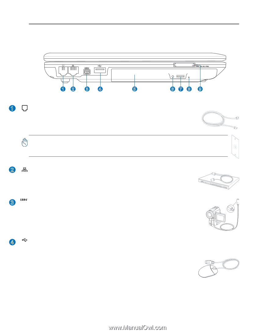
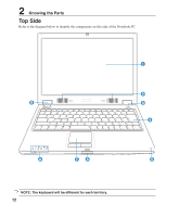
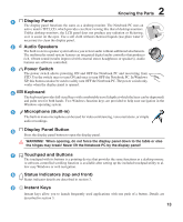
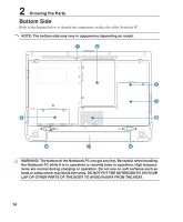
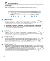
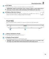
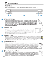
2 Knowing the Parts Left Side Refer to the diagram below to identify the components on this side of the Notebook PC. 12 34 5 678 9 1 Modem Port The RJ-11 modem port with two pins is smaller than the RJ-45 LAN port and supports a standard telephone cable. The internal modem supports up to 56K V.90 transfers. The built-in connector allows convenient use without additional adapters. IMPORTANT! The built-in modem does not support the voltage used in digital phone systems. Do not connect the modem port to a digital phone system or else damage will occur to the Notebook PC. 2 LAN Port The RJ-45 LAN port with eight pins is larger than the RJ-11 modem port and supports a standard Ethernet cable for connection to a local network. The built-in connector allows convenient use without additional adapters. 3 IEEE1394 Port IEEE1394 is a high speed serial bus like SCSI but has simple connections and hot- plugging capabilities like USB. The interface IEEE1394 has a bandwidth of 100-400 Mbits/sec and can handle up to 63 units on the same bus. IEEE1394 is also used in high-end digital equipment and should be marked "DV" for Digital Video port. 4 2.0 USB Port (2.0/1.1) The USB (Universal Serial Bus) port is compatible with USB 2.0 or USB 1.1 devices such as keyboards, pointing devices, cameras, hard disk drives, printers, and scanners connected in a series up to 12Mbits/sec (USB 1.1) and 480Mbits/sec (USB 2.0). USB allows many devices to run simul- taneously on a single computer, with some peripherals acting as additional plug-in sites or hubs. USB supports hot-swapping of devices so that most peripherals can be connected or disconnected without restarting the computer. 16
-
 1
1 -
2
-
3
-
4
-
5
-
6
-
7
-
8
-
9
-
10
-
 11
11 -
 12
12 -
 13
13 -
 14
14 -
 15
15 -
 16
16 -
 17
17 -
 18
18 -
 19
19 -
 20
20 -
 21
21 -
22
-
23
-
24
-
25
-
26
-
27
-
28
-
29
-
30
-
31
-
32
-
33
-
34
-
35
-
36
-
37
-
38
-
39
-
40
-
41
-
42
-
43
-
44
-
45
-
46
-
47
-
48
-
49
-
50
-
51
-
52
-
53
-
54
-
55
-
56
-
57
-
58
-
59
-
60
-
61
-
62
-
63
-
64
-
65
-
66
-
67
-
68
-
69
 |
 |