Asus Z81S A4S Hareware User's Manual for English Edition (E2014) - Page 18
Asus Z81S Manual
 |
View all Asus Z81S manuals
Add to My Manuals
Save this manual to your list of manuals |
Page 18 highlights
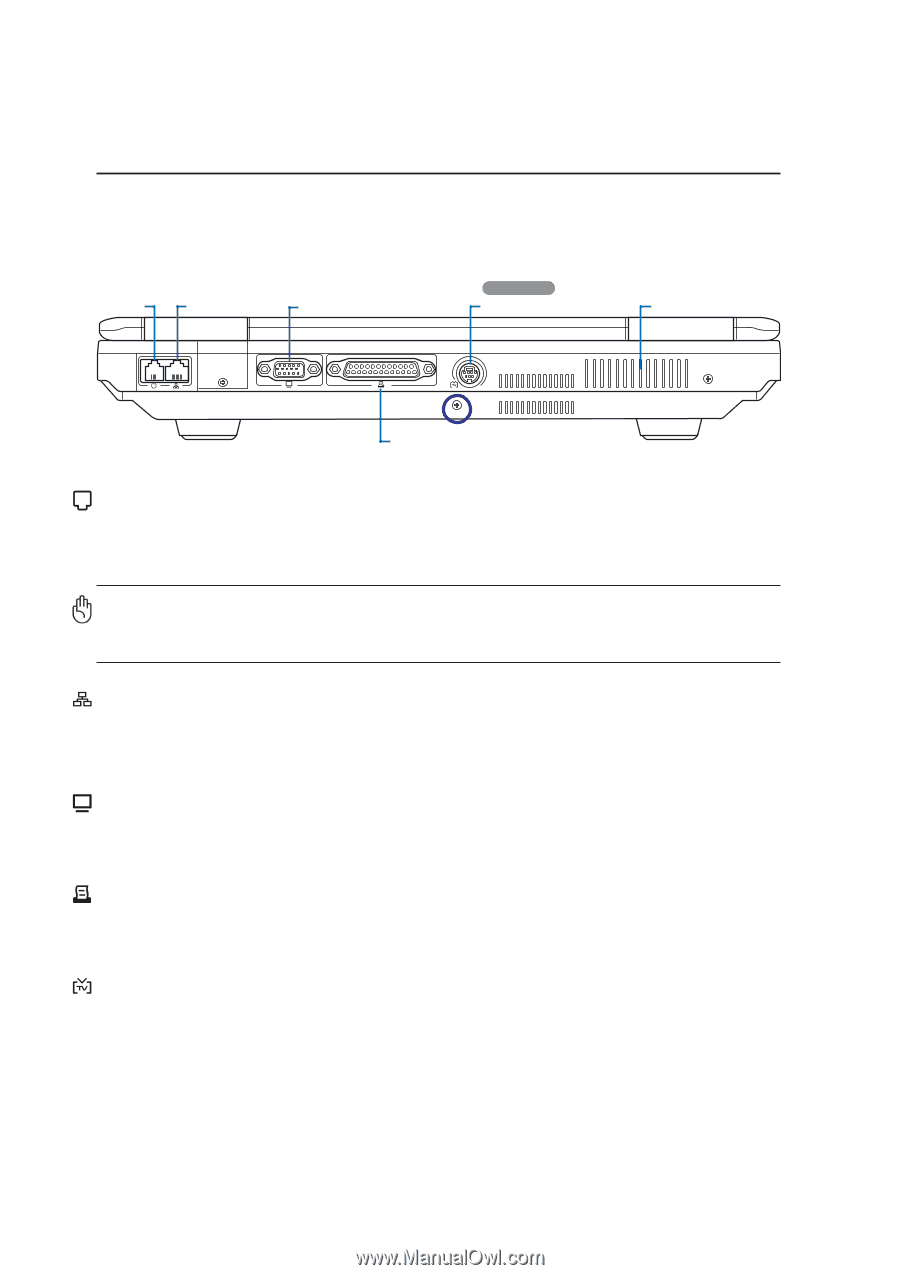
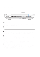
2 Knowing the Parts Rear Side Refer to the diagram below to identify the components on this side of the Notebook PC. On selected models Modem Port LAN Port Monitor Port TV Out Port Air Vents Parallel Port Modem Port The RJ-11 modem port with two pins is smaller than the RJ-45 LAN port and supports a standard telephone cable. The internal modem supports up to 56K V.90 transfers. The built-in connector allows convenient use without additional adapters. IMPORTANT! The built-in modem does not support the voltage used in digital phone systems. Do not connect the modem port to a digital phone system or else damage will occur to the Notebook PC. LAN Port The RJ-45 LAN port with eight pins is larger than the RJ-11 modem port and supports a standard Ethernet cable for connection to a local network. The built-in connector allows convenient use without additional adapters. Display (Monitor) Output The 15-pin D-sub monitor port supports a standard VGA-compatible device such as a monitor or projector to allow viewing on a larger external display. Parallel Port The 25-pin D-sub parallel/printer port supports native parallel devices such as laser/inkjet printers, or parallel-adapted device such as external hard drives, removable drives, or scanners. TV-Out Port (on selected models) The TV-Out port is an S-Video connector that allows routing the Notebook PC's display to a television or video projection device. You can choose between simultaneouly or single display. Use an S-Video cable (not provided) for high quality displays or use the provided RCA to S-Video adapter for standard video devices. This port supports both NTSC and PAL formats. 18
-
 1
1 -
2
-
3
-
4
-
5
-
6
-
7
-
8
-
9
-
10
-
11
-
12
-
 13
13 -
 14
14 -
 15
15 -
 16
16 -
 17
17 -
 18
18 -
 19
19 -
 20
20 -
 21
21 -
 22
22 -
 23
23 -
24
-
25
-
26
-
27
-
28
-
29
-
30
-
31
-
32
-
33
-
34
-
35
-
36
-
37
-
38
-
39
-
40
-
41
-
42
-
43
-
44
-
45
-
46
-
47
-
48
-
49
-
50
-
51
-
52
-
53
-
54
-
55
-
56
-
57
-
58
-
59
-
60
-
61
-
62
-
63
-
64
-
65
-
66
-
67
-
68
-
69
-
70
-
71
-
72
-
73
-
74
-
75
-
76
 |
 |