Audiovox FPE1906DV Operating Instructions - Page 9
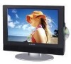
Audiovox FPE1906DV - 19" LCD TV Manual
 |
UPC - 044476034275
View all Audiovox FPE1906DV manuals
Add to My Manuals
Save this manual to your list of manuals |
Page 9 highlights
Rear Panel 1. Y/Pb/Pr Input Jack Connected to the Y/Pb/Pr input in Component mode. 2. L/R Audio Input Jack Connected to the L/R audio input in Component mode. 3. AV Output Jacks Connected to the external AV input device. 4. AV and S-Video Input Jacks In the S-VIDEO mode, connected to S-VIDEO signal input. In the CVBS mode, connected to the external video signal input. The L/R audio input jacks can be used in the both S-VIDEO and CVBS modes. 5. TV Signal Input Jack Connected for the external NTSC TV signal input. 6. DC 12V In Jack Connected to power adapter. 7. VGA Input Jack Connected to the VGA output jack on a personal computer. 8. PC AUDIO Input Jack Connected to the PC audio output jack. -8-
-
 1
1 -
2
-
3
-
 4
4 -
 5
5 -
 6
6 -
 7
7 -
 8
8 -
 9
9 -
 10
10 -
 11
11 -
 12
12 -
 13
13 -
 14
14 -
15
-
16
-
17
-
18
-
19
-
20
-
21
-
22
-
23
-
24
-
25
-
26
-
27
-
28
-
29
-
30
-
31
-
32
-
33
-
34
-
35
-
36
-
37
-
38
-
39
-
40
-
41
-
42
-
43
-
44
 |
 |

- 8 -
Rear Panel
1. Y/Pb/Pr Input Jack
Connected
to
the
Y/Pb/Pr
input
in
Component mode.
2.
L/R Audio Input Jack
Connected to the L/R audio input in
Component mode.
3. AV Output Jacks
Connected to the external AV input device.
4.
AV and S-Video Input Jacks
In the S-VIDEO mode, connected to
S-VIDEO signal input.
In the CVBS mode, connected to the
external video signal input.
The L/R audio input jacks can be used in the
both S-VIDEO and CVBS modes.
5. TV Signal Input Jack
Connected for the external NTSC TV
signal input.
6. DC 12V In Jack
Connected to power adapter.
7. VGA Input Jack
Connected to the VGA output jack on a
personal computer.
8.
PC AUDIO Input Jack
Connected to the PC audio output jack.