Audiovox VBDV56 Owners Manual - Page 5
E. Controls, Indicators, and Connectors, F. Powering the Unit
 |
UPC - 044476013690
View all Audiovox VBDV56 manuals
Add to My Manuals
Save this manual to your list of manuals |
Page 5 highlights
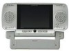
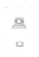
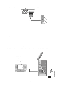
E. Controls, Indicators, and Connectors (Refer to Figure 3) MONITOR RIGHT SIDE 1) Brightness UP/DOWN Thumbwheel 2) Volume UP/DOWN Thumbwheel 3) Headphone Input # 2 4) Headphone Input # 1 MONITOR FRONT SIDE 5) REMOTE CONTROL SENSOR 6) DVD/AV and VCP SELECT Switch Right Side MONITOR LEFT SIDE 7) POWER ON/OFF BUTTON (Monitor) 8) RIGHT AUDIO IN (Monitor) 9) LEFT AUDIO IN (Monitor) 10) VIDEO IN (Monitor) 11) MONITOR JACK (Input) 12) DC 12V INPUT (Monitor) F. Powering the Unit Option 1 Indoor Power (Refer to Figure 4) Front Side Left Side Figure 4 Using the AC/DC adapter supplied with the VBDV56, plug the connector end into the DC 12V IN jack on the side of the Monitor. Plug the AC/ DC adapter into a 120V AC power receptacle. This can be done with the Monitor inside or outside the pouch. 4
-
 1
1 -
 2
2 -
 3
3 -
 4
4 -
 5
5 -
 6
6 -
 7
7 -
 8
8 -
 9
9 -
 10
10 -
 11
11
 |
 |
