Behringer 150 RING MOD/NOISE/S&H/LFO Quick Start Guide
Behringer 150 RING MOD/NOISE/S&H/LFO Manual
 |
View all Behringer 150 RING MOD/NOISE/S&H/LFO manuals
Add to My Manuals
Save this manual to your list of manuals |
Behringer 150 RING MOD/NOISE/S&H/LFO manual content summary:
- Behringer 150 RING MOD/NOISE/S&H/LFO | Quick Start Guide - Page 1
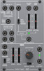
Quick Start Guide 150 RING MOD/NOISE/S&H/LFO Legendary Analog Ring Modulator/ Noise/S&H/LFO Module for Eurorack Controls (6) (7) (8) (10) (1) (2) (9) (3) (11) (4) (5) (12) (18) (13) (15) (20) (14) (9) CLOCK RATE slider controls the internal clock signal's rate before the clock signal - Behringer 150 RING MOD/NOISE/S&H/LFO | Quick Start Guide - Page 2
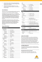
Connections Ring modulator Ext signal X / Y X Impedance Y impedance Maximum level R.M out Impedance Maximum level Noise jack 1 kΩ unbalanced LFO Freq CV in Impedance CV input range LFO out Impedance Output level Controls S & H Clock rate Lag time Ext / LFO / noise LFO Freq range Frequency Delay
-
 1
1 -
 2
2
 |
 |

Quick Start Guide
150 RING MOD/NOISE/S&H/LFO
Legendary Analog Ring Modulator/
Noise/S&H/LFO Module for Eurorack
Controls
(1)
EXT SIG X/NOISE
jack routes audio signals or noise into the
ring modulator. The audio signal or noise coming in through
the EXT SIG X/NOISE jack is combined with and modulated
by the carrier signal routed into the EXT SIG Y/LFO jack.
(2)
EXT SIG Y/LFO
jack routes the carrier signal into the
ring modulator. The carrier signal can be in the audio
range, such as a 500 Hz sine wave, or a signal from
Low Frequency Oscillator (LFO).
(3)
R.M OUT
jack sends out the final ring modulator signal.
(4)
PINK
output jacks offer dual white pink noise outputs for
use other modules.
(5)
WHITE
output jacks offer dual white noise outputs for use
with other modules.
(6)
EXT SIG
input jack routes external signals into the S&H
circuit for processing. Use the EXT/LFO/NOISE switch to
optimize the EXT SIG input for different types of signals.
(7)
EXT/LFO/NOISE
sliding switch optimizes the EXT SIG for use
with control signals (EXT), signals from a Low Frequency
Oscillator (LFO) or noise signals (NOISE).
(8)
CLOCK OUT
jack sends out a clock signal generated inside
the S&H circuit.
(9)
CLOCK RATE
slider controls the internal clock signal’s rate
before the clock signal is routed out through the CLOCK
OUT jack.
(10)
S&H OUT
jack sends out the final S&H (Sample & Hold)
signal over cables with 3.5 mm TS connectors.
(11)
LAG TIME
slider can be used to smooth out the changes
between control voltage values as the slider is raised,
similar to a portamento or glide effect on a keyboard.
(12)
EXT CLOCK IN
input jack routes an external clock signal into
the S&H circuit.
(13)
WAVEFORM
knob selects between sine, triangle, square,
ramp and sawtooth waveforms for the LFO.
(14)
FREQ RANGE
sliding switch selects between high (H),
mid (M) and low (L) frequency ranges.
(15)
TRIGGER
jack allows a control voltage to trigger the LFO
waveform by resetting the amplitude to 0. The waveform
then returns to the original amplitude at a rate set by the
DELAY slider.
(16)
FREQ
slider fine-adjusts the LFO frequency within the range
chosen by the FREQ RANGE switch.
(17)
DELAY
slider controls the amount of time that elapses
between the beginning of a new note and the LFO’s
amplitude peak.
(18)
FREQ CV IN
input jack allows a control voltage to control
the LFO frequency in place of the FREQ slider.
(19)
OUTPUT LEVEL
sliding switch selects between a
full-strength LFO output signal (x1 setting) and a
1/10th-strength signal (x 1/10 setting).
(20)
LFO OUT
output jacks offer dual LFO outputs for use with
cables with 3.5 mm TS connectors.
Power Connection
The 150 RING MOD/NOISE/S&H/LFO module comes with the
required power cable for connecting to a standard Eurorack power
supply system. Follow these steps to connect power to the module.
It is easier to make these connections before the module has been
mounted into a rack case.
1.
Turn the power supply or rack case power off
and disconnect
the power cable.
2.
Insert the 16-pin connector on the power cable into the
socket on the power supply or rack case. The connector has
a tab that will align with the gap in the socket, so it cannot
be inserted incorrectly. If the power supply does not have
a keyed socket, be sure to orient pin 1 (-12 V) with the red
stripe on the cable.
(1)
(3)
(4)
(
10
)
(8)
(6) (7)
(2)
(9)
(14)
(16) (17)
(19)
(20)
(13)
(12)
(18)
(15)
(11)
(5)