Behringer 297 DUAL PORTAMENTO/CV UTILITIES Quick Start Guide - Page 1
Behringer 297 DUAL PORTAMENTO/CV UTILITIES Manual
 |
View all Behringer 297 DUAL PORTAMENTO/CV UTILITIES manuals
Add to My Manuals
Save this manual to your list of manuals |
Page 1 highlights
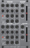
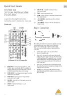
Quick Start Guide SYSTEM 100 297 DUAL PORTAMENTO/ CV UTILITIES Legendary Analog Portamento Controller and CV Utilities for Eurorack Controls (1) (2) (3) (6) NON INV OUT - Send the mix of inputs 1-4 as a non-inverted signal. (7) TIME - Adjust the portamento time. (8) CV IN - Connect a voltage to control the portamento time from another module. (9) +10/-10 V LEVEL - Adjust the level of the +10 V and -10 V outputs. (10) +10/-10 V OUT - Send the +10 V and -10 V signals via 3.5 mm TS cable. Power Connection (4) (5) (7) (6) (8) (9) (10) (1) MIXER SIG IN - Connect incoming signals via 3.5 mm TS cables. Inputs 3 and 4 feed +10/-10 V respectively to the mixer inputs if no jack is inserted, which can be used to offset the overall mixer output control voltage. (2) PORTA SIG OUT - Send the portamento signal to another module via 3.5 mm TS cable. (3) PORTA SIG IN - Connect a signal to the portamento section via 3.5 mm TS cable. (4) SIG LEVEL - Adjust the level of the signals connected to the mixer inputs. (5) INV OUT - Send the mix of inputs 1-4 as an inverted signal. The module comes with the required power cable for connecting to a standard Eurorack power supply system. Follow these steps to connect power to the module. It is easier to make these connections before the module has been mounted into a rack case. 1. Turn the power supply or rack case power off and disconnect the power cable. 2. Insert the 16-pin connector on the power cable into the socket on the power supply or rack case. The connector has a tab that will align with the gap in the socket, so it cannot be inserted incorrectly. If the power supply does not have a keyed socket, be sure to orient pin 1 (-12 V) with the red stripe on the cable. 3. Insert the 10-pin connector into the socket on the back of the module. The connector has a tab that will align with the socket for correct orientation. 4. After both ends of the power cable have been securely attached, you may mount the module in a case and turn on the power supply. V 1.0
-
 1
1 -
 2
2
 |
 |
