Behringer CABLE TESTER CT100 Manual - Page 3
Installed Cable Tester Mode, Test Tone Mode - use cable tester
 |
View all Behringer CABLE TESTER CT100 manuals
Add to My Manuals
Save this manual to your list of manuals |
Page 3 highlights
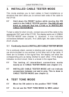
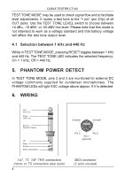
CABLE TESTER CT100 3. INSTALLED CABLE TESTER MODE This mode enables you to test cables in fixed installations or situations that don’t allow you to connect both ends of the cable to the CT100. + Hold down the RESET button while moving the ON switch to the CABLE TESTER position. The ON LED will blink to indicate that the CT100 is in INSTALLED CABLE TESTER MODE. To test a cable for short circuits, connect one end of the cable to the appropriate OUT jack of the CT100. The display works as in CABLE TESTER MODE (see chapter 2). However, it now indicates connections between out pins. If no LEDs light, the cable is free of short circuits. 3.1 Continuity check in INSTALLED CABLE TESTER MODE For a continuity check, connect a shorting jack (a jack in which pins are short-circuited to one another) to the other end of the cable. If there are no breaks in the signal flow, the display will show the corresponding pins as being shorted to each other. If the display indicates no short circuit, there is a break in the signal flow. + The testing of intermittent connections works exactly as in CABLE TESTER MODE (see chapter 2.1). + INSTALLED CABLE TESTER MODE will not indicate connections between out and in pins. This is done in CABLE TESTER MODE (see chapter 2). 4. TEST TONE MODE + Move the ON switch to the position TEST TONE. + Do not use the TEST TONE MODE for MIDI cables! 3
-
 1
1 -
 2
2 -
 3
3 -
 4
4 -
 5
5 -
 6
6 -
 7
7
 |
 |
