Behringer CONTROL2USB Quick Start Guide - Page 6
XENYX CONTROL2USB Controls - studio monitor controller
 |
View all Behringer CONTROL2USB manuals
Add to My Manuals
Save this manual to your list of manuals |
Page 6 highlights
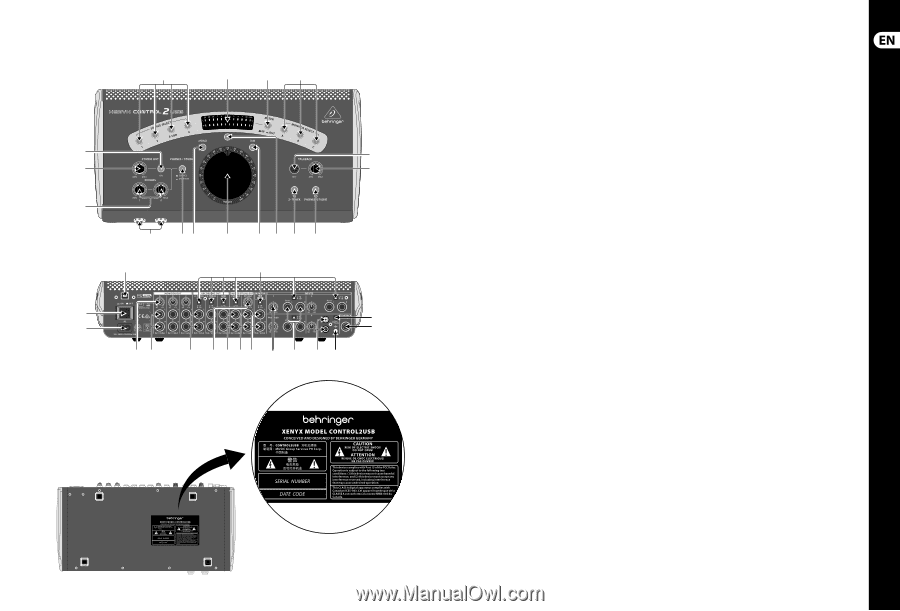
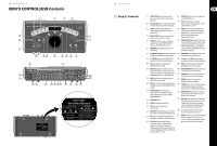
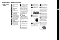
10 XENYX CONTROL2USB XENYX CONTROL2USB Controls (1) (2) (3) (4) (16) (5) (17) (6) (15) (14) (13) (12) (10) (9) (11) (8) (7) (18) (19) (34) (24) (33) (23) (32) (31) (30) (20) (29) (28) (27) (21) (22) (26) (25) 11 Quick Start Guide (EN) Step 2: Controls (1) SOURCE SELECT buttons determine which input source will be routed to outputs on the back panel. (2) LEVEL METERS shows the input or output signal strength of the active connected stereo source. (20) STUDIO OUT trim knob adjusts the signal sent via the STUDIO OUT jacks. (21) TRIM control knob adjusts the input sensitivity of the incoming signal by +/-10 dB (same for INPUTS 2, 3 and 4). (3) METER switch determines whether the input or output signal will be shown on the LEVEL METERS. (4) MONITOR SELECT activates or deactivates the speakers connected to A, B or C outputs. (5) TALKBACK microphone allows a microphone signal to be sent to the PHONES/STUDIO OUT outputs or the RECORDING OUT outputs. (6) TALKBACK level knob adjusts the gain of the TALKBACK MIC. (22) INPUT 1 jacks for connecting a balanced or unbalanced stereo signal. If a mono signal is plugged into the L input, it is automatically routed to the left and right inputs (same for INPUTS 2 and 3). (23) TALKBACK FOOTSW input jack for connecting remote TALKBACK mic switch. When the switch is activated, the talkback circuit opens for the PHONES/STUDIO OUT outputs, both PHONES outputs and the three RECORDING OUT outputs (2-TRACK A, B and DAW). (7) TO PHONES/STUDIO button sends the TALKBACK (24) LINE/PHONO switch changes the input source MIC signal to the PHONES and STUDIO outputs. from (unbalanced) line to phono level. (8) TO 2-TRACK button sends the TALKBACK MIC signal to the 2-TRACK A, B and DAW outputs. (25) Grounding Screw (GND) for connecting the grounding wire from the attached phonograph. (9) DIM switch reduces the signal going to MONITOR A, B and C by 20 dB. (26) INPUT 4 stereo RCA inputs for connecting a phonograph or other stereo line signal. (10) VOLUME knob adjusts the volume of signals going to the Monitor A, B and C outputs. It does not affect the volume of the signal going to the RECORDING OUT, PHONES, or STUDIO OUT jacks. (11) MUTE switch silences the signal going to the MONITOR A, B, and C outputs. (12) MONO switch turns the stereo input signal into a monophonic signal out of the MONITOR A, B and C outputs. (13) PHONES/STUDIO switch changes the signal being fed to the PHONES and STUDIO outputs between the input sources and the MONITOR MIX INPUT. (14) HEADPHONE jacks. (15) PHONES volume adjustment knobs. (16) ON button turns the signal to the STUDIO OUT jacks. (17) STUDIO OUT volume knob adjusts the volume of the speakers connected to the STUDIO OUT jacks. (18) USB jack for connecting your CONTROL2USB to the computer, working as a 2-in/2-out soundcard. (19) 2-TRACK A +4/-10 level switch changes between the balanced +4 dB professional equipment standard and the unbalanced -10 dB consumer equipment standard (same for 2-TRACK B, DAW outputs, PHONES, MONITOR MIX inputs and INPUTS 1, 2 and 3). (27) MONITOR MIX INPUT allows the connection of an alternate stereo mix from the DAW. (28) STUDIO OUT jacks for connecting speakers in a recording space for monitoring and talkback. (29) PHONES output jacks for connecting a headphone distribution amplifier. (30) 2-TRACK A output jacks for sending a balanced or unbalanced stereo signal to an external recorder (same for 2-TRACK B and DAW outputs). (31) MONITOR OUT A output jacks for connecting powered speakers or an amplifier for passive speakers (same for B and C). (32) MONITOR A trim knob adjusts the MONITOR A output signal between the professional +4 dB standard to the -10 dB consumer standard. It allows the balancing of signal between the three monitor outputs (same for B and C). (33) Connect the included IEC connector to this AC socket and a suitable power source. (34) POWER switch turns the unit on and off. When in the off (standby) position, the circuits are still live. To remove power altogether, remove the power cord from the AC mains supply.
-
 1
1 -
 2
2 -
 3
3 -
 4
4 -
 5
5 -
 6
6 -
 7
7 -
 8
8 -
 9
9 -
 10
10 -
 11
11 -
 12
12 -
13
-
14
-
15
-
16
-
17
 |
 |