Behringer DCX2496LE Manual - Page 6
Activating LOCK and/or GLOBAL LOCK automatically locks all STORE
 |
View all Behringer DCX2496LE manuals
Add to My Manuals
Save this manual to your list of manuals |
Page 6 highlights
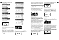
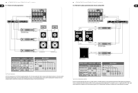
10 ULTRADRIVE PRO DCX2496/ULTRADRIVE DCX2496LE User Manual Press OK or CANCEL to subsequently copy further pages in the same way. ◊ Only similar pages with identical parameters can be copied. If you select a SOURCE PAGE that is not available in the DESTINATION CHANNEL, the display will read NOT AVAILABLE under DESTINATION PAGE. To lock a parameter page you must activate the PAGE LOCK function (ON). The unit will prompt you to enter a password. Use the data wheel to enter a password with a maximum of 8 characters, and confirm your selection with OK. ◊ CAUTION: Please make a note of your password. It is impossible to unlock parameter pages without the correct password! Fig. 4.17: Setup ➠ Copy If you set COPY MODE to WHOLE CHANNEL, you can copy the complete channel settings to another channel. Use SOURCE to select the channel to be copied (SOURCE-CHANNEL), then define the channel to be overwritten (DESTINATION). The process is the same as in PAGE mode. So-called "cross copying" (copying of different channels, for example output 1 to input A), allows the copying of only those pages that can be transferred 1:1 to another channel. Any other pages will not be overwritten. Previously locked pages (see chapter 4.2.4) cannot be overwritten. A corresponding message is displayed. Fig. 4.18: Setup ➠ Copy 4.2.4 PAGE LOCK In this menu you can lock individual parameter pages, preventing them from being edited without first entering a password. This is useful for P.A. rental companies, for example, who want to make sure that certain "harmful" pages with necessary fixed settings cannot be accessed by the user. Fig. 4.21: Setup ➠ Page Lock Now, the parameter SELECT PAGES is displayed, enabling you to select all the pages to be locked. Use the IN/OUT/SUM/SETUP buttons to call up a menu, the data wheel to select the page of your choice and the OK button to activate the PAGE LOCK function. The data wheel also allows you to scroll through a list of all pages, from which you can select the ones you wish to lock. This is the only way to call up the ALL PAGES function that lets you lock all pages in one operation. To unlock all pages at once, select ALL PAGES and press CANCEL. As before, the selected pages must be confirmed and locked with OK. Locked pages are displayed with a closed lock symbol. If a page is unlocked, the lock symbol is open. Use the CANCEL button to unlock a previously locked page. ◊ The OK and CANCEL functions cannot be selected in the display with the cursor. They can only be activated with the corresponding buttons on the front panel. Use the CHECK function for an overview of all locked pages. The locked pages from the list now appearing can be selected with the data wheel. This function is located at the bottom right of the display and must be selected with the cursor. When you call up a locked page, you will at first notice no difference. Only when you try to edit a parameter, will the display prompt you to enter your password. Entering the correct password and confirming it with OK will take you back to the page, now ready for editing. To activate PAGE LOCK again, go to the PAGE LOCK page (4/6) and enter your password again. Now, all settings are available, i.e. you can activate or deactivate PAGE LOCK completely by selecting the line "PAGE LOCK: ON" with the cursor and setting this parameter to ON or OFF with the data wheel. Fig. 4.19: Setup ➠ Page Lock In the PAGE LOCK menu you can either lock single pages or all pages. In this case, you need a password to edit the pages. The parameter PAGE LOCK is set to OFF by default. As long as it is not ON, you can skip this page and move on to the next. 4.2.5 GLOBAL LOCK This function allows you to lock all parameter pages if you want to make sure that nobody can edit your settings while you're away during a break in a live performance, for example. Fig. 4.20: Setup ➠ Page Lock Fig. 4.22: Setup ➠ Global Lock 11 ULTRADRIVE PRO DCX2496/ULTRADRIVE DCX2496LE User Manual On this SETUP page you can activate the GLOBAL LOCK function (ON), enter a password, then confirm with OK. Now, if you try to edit any parameter, the display will prompt you to enter your password. The process follows the same logic as the PAGE LOCK routine. 2. LINK (RS-485) Fig. 4.27: Setup ➠ Miscellaneous Fig. 4.23: Setup ➠ Global Lock ◊ Activating PAGE LOCK and/or GLOBAL LOCK automatically locks all STORE and RECALL pages. CAUTION: If you have locked individual pages with PAGE LOCK and deactivated the GLOBAL LOCK function with the correct password, you can not yet make any changes to the corresponding page. You must first unlock this page in the PAGE LOCK menu. When using the GLOBAL LOCK feature, we recommend that you unlock all pages in the PAGE LOCK menu (UNLOCK ALL). 4.2.6 MISCELLANEOUS LINK (RS-485) = PC DCX2496 RS-485 DEVICE ID: 1 PORT: LINK (RS-485) RS-485 DCX2496 TERM-Switch: ON DEVICE ID: 2 PORT: LINK (RS-485) RS-485 DCX2496 DEVICE ID: 3 PORT: LINK (RS-485) Fig. 4.24: Setup ➠ Miscellaneous On this page, the current version of your DCX2496 operating software is shown in the top right corner of the display (e.g. VERSION: 1.0). This is just a message and cannot be selected. Additionally, this menu provides five user settings. Firstly, you can adapt the CONTRAST of the display to ambient conditions. Secondly, you can assign a DEVICE ID to your DCX2496, allowing you to daisy-chain several units via the rear panel RS-485 network interface (LINK A and B). The first unit is connected to a PC either via one of the LINK interfaces (RS-485) or via the RS-232 interface. Note - The DCX2496LE does not have RS-232 or RS-485 connectors. The PORT parameter provides three different modes for the PC remote control: 1. PC (RS-232) Fig. 4.28: LINK (RS-485) mode Please use this mode when several ULTRADRIVE PROs are linked to each other via the network interfaces LINK A and B and the first unit in the chain is connected to a computer via the RS-485 interface. The last unit in the chain must have a termination (TERM switch on rear panel = ON). The RS-232 interface is not used in this configuration. 3. PC -> LINK Fig. 4.29: Setup ➠ Miscellaneous Fig. 4.25: Setup ➠ Miscellaneous PC (RS-232) = PC DCX2496 RS-232 DEVICE ID: 1 PORT: PC (RS-232) Fig. 4.26: PC (RS-232) mode Use this setting if you want to connect only one DCX2496 to your computer via the RS-232 interface. It is impossible to daisy-chain several units in this mode. TERM-Switch: ON PC -> LINK = PC RS-232 DCX2496 DEVICE ID: 1 PORT: PC -> LINK RS-232 DCX2496 TERM-Switch: ON DEVICE ID: 2 PORT: LINK (RS-485) RS-232 DCX2496 DEVICE ID: 3 PORT: LINK (RS-485) Fig. 4.30: PC -> LINK mode
-
 1
1 -
 2
2 -
 3
3 -
 4
4 -
 5
5 -
 6
6 -
 7
7 -
 8
8 -
 9
9 -
 10
10 -
 11
11 -
 12
12 -
13
-
14
-
15
-
16
-
17
-
18
-
19
 |
 |
