Behringer DEQ2496 Quick Start Guide - Page 5
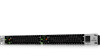
ULTRACURVE PRO DEQ2496 Controls - power supply
 |
View all Behringer DEQ2496 manuals
Add to My Manuals
Save this manual to your list of manuals |
Page 5 highlights
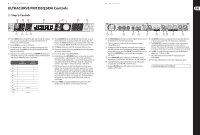
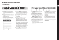
8 ULTRACURVE PRO DEQ2496 ULTRACURVE PRO DEQ2496 Controls (EN) Step 2: Controls (1) (3) (6) (8) (9) (10) (11) 9 Quick Start Guide (2) (5) (4) (7) (1) The LED METER indicates the DEQ2496's input signal. The top CLIP LED lights up as soon as the input signal level is too high or the peak limiter in the Dynamics menu has been activated. (2) Use the METER key to select the METER menu. (3) The DEQ2496 features a built-in real-time analyzer displaying the entire frequency range. Use the RTA key to select the corresponding menu and adjust the various settings. (4) Depending on the currently selected menu, the COMPARE key allows you to compare either complete presets or individual modules. The following table shows how the COMPARE key works in each module. GEQ PEQ DEQ FBD WIDTH DYN UTIL I/O BYPASS RTA MEMORY METER COMPARE (complete preset) COMPARE (module only) x x x x x x x x x not active x not active (5) Press the MEMORY key to select the MEMORY menu. Here, you can save or recall complete presets or individual modules from one preset (e.g. GEQ, PEQ etc.). The MEMORY LED lights up as soon as the parameter values of the preset selected in the MEMORY menu differ from currently active settings. (6) The PAGE key allows you to select the various pages within one menu. (7) The functions performed by the keys A and B depend on the selected menu and are indicated in the display. (8) This is the LC display of your ULTRACURVE PRO (9) The DEQ2496 has three DATA WHEELS, which can be used to select and edit various parameters-again depending on the currently selected menu. Often, they perform a dual function, i.e. you can edit by turning and pressing a data wheel. Pressing the data wheels also changes the scaling of many parameters (step width) or confirms/resets previously made entries. (10) With the menu keys you can select the individual menus of the various modules. They can also be used to select specific pages from these menus (like PAGE key). Each of these keys has a built-in LED, which lights up when the corresponding module starts modifying the sound. When the DEQ2496 receives MIDI data, the LED of the UTILITY key lights up briefly. Keep this key pressed for about 1 s to bypass active modules or re-activate disabled ones. This function refers only to those modules which can be edited in the BYPASS menu. (11) Use the POWER switch to put the DEQ2496 into operation. This switch should be set to "Off" before you connect the unit to the mains. (12) (13) (14) (15) (16) (17) (18) (19) (20) (21) (22) (12) The FUSE HOLDER holds the mains fuse of the DEQ2496. Blown fuses must be replaced by fuses of the same type and rating. (13) The mains connection is made using the enclosed power cord and a standard IEC receptacle. (14) The MIDI jacks enable the DEQ2496 to communicate with a computer or other MIDI equipment. Incoming MIDI data are received on the MIDI IN, outgoing MIDI data are sent via the MIDI OUT. Received MIDI data are also present at the MIDI THRU jack, so as to pass them on unmodified to other devices. (15) Use the WORDCLOCK input to synchronize your DEQ2496 to external equipment via a wordclock signal. This connector is on a BNC coaxial jack. (16) Your DEQ2496 features a digital optical interface for the transmission/ reception of data in both AES/EBU and S/PDIF formats. (17) The digital AES/EBU interface (XLR connectors) also sends/receives AES/EBU or S/PDIF signals. (18) The AUX OUT phone jack is an additional stereo output, which allows you to tap the audio signal present at the digital outputs in analog form. (19) The RTA/MIC IN XLR connector can be used to connect a measurement microphone providing an input signal for the real-time analyzer or SPL meter. This connector has a switchable +15 V phantom power supply for condenser microphones and can be set to microphone or line sensitivity. (20) The MAX switch raises the maximum level present at the MAIN inputs/ outputs from +12 dBu to +22 dBu. (21) These balanced XLR connectors provide the analog output signal of the DEQ2496. (22) These balanced XLR inputs are used to connect analog input signals. Check Out behringer.com for Full Manual
-
 1
1 -
 2
2 -
 3
3 -
 4
4 -
 5
5 -
 6
6 -
 7
7 -
 8
8 -
 9
9 -
 10
10 -
 11
11 -
12
-
13
-
14
-
15
-
16
 |
 |
