Behringer EURODESK SX2442FX Manual - Page 14
Audio Connectors - pro
 |
View all Behringer EURODESK SX2442FX manuals
Add to My Manuals
Save this manual to your list of manuals |
Page 14 highlights
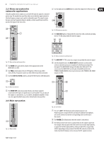
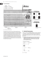
14 EURODESK SX3242FX/SX2442FX User Manual 4.2 Live set-up Drums Bass K S O O I N V V C A E E K R R R E H H D E E R A A U D D M L R Guitar Vocals 1 Vocals 2 Keyboard LR EUROPOWER EP1500 2 x EUROLIVE PROFESSIONAL Stack (B1800X PRO & B1220 PRO) EUROPOWER EP1500 SUB 1-2 switch pressed SUB/MAIN switches not pressed Fig. 4.2: Wiring the console for live operation MAIN switch pressed This example shows a classic live set-up. As in the studio example, four drum microphones, bass, keyboard (stereo channel), guitar and two vocal microphones are connected. The four drum channels (kick drum, snare, overhead L, overhead R) are mixed down to two subgroups and then routed to the main mix. This way, it is possible to conveniently control the volume of the entire drums in the main mix with the two subgroup faders. The built-in compressor insert effect is used for the bass. The corresponding input channel is separate from all buses and the bass signal is routed directly from the internal effects processor to the main mix bus. The MAIN/SUB switch must not be pressed in this case and the position of the SUB 1/2 SUB 3/4 switch is irrelevant. L/R switch pressed EUROLIVE PROFESSIONAL B1220 PRO 5. Audio Connectors The inputs and outputs of the BEHRINGER EURODESK are designed as unbalanced ¼" TS connectors-except for the balanced line inputs of the mono and stereo channels and the main out connectors. Of course, all inputs and outputs work with both balanced and unbalanced connectors. The tape ins and outs are stereo RCA connectors. ◊ Please ensure that only qualified personnel install and operate the EURODESK. During installation and operation, the user must have sufficient electrical contact to earth. Electrostatic charges might affect the operation of the unit. Unbalanced ¼" TS connector strain relief clamp sleeve tip sleeve (ground/shield) tip (signal) Fig. 5.1: ¼" TS connector
-
 1
1 -
2
-
3
-
4
-
5
-
6
-
7
-
8
-
 9
9 -
 10
10 -
 11
11 -
 12
12 -
 13
13 -
 14
14 -
 15
15 -
 16
16 -
 17
17 -
 18
18 -
 19
19 -
20
 |
 |
