Behringer EURODESK SX2442FX Manual - Page 9
Mono out for, subwoofer applications, Main out - case
 |
View all Behringer EURODESK SX2442FX manuals
Add to My Manuals
Save this manual to your list of manuals |
Page 9 highlights
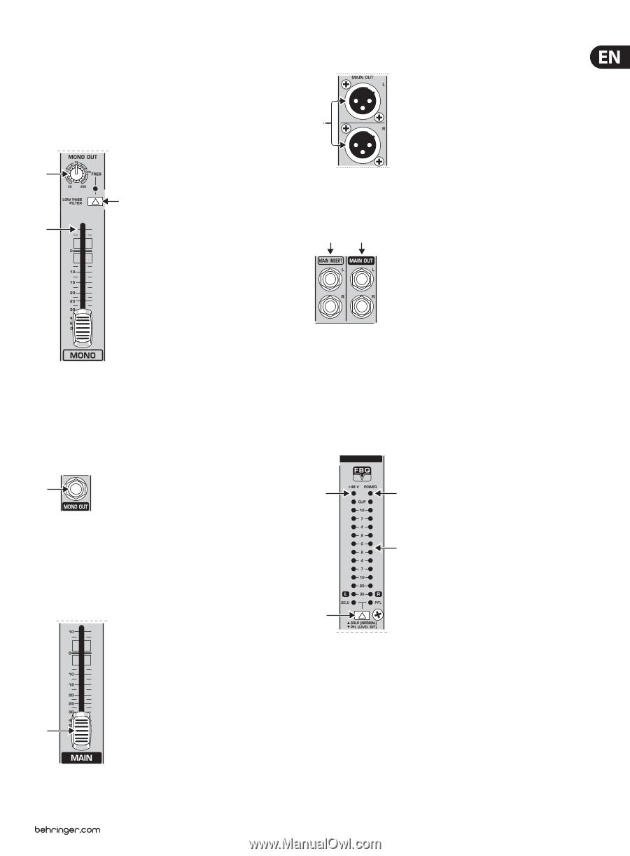
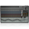
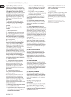
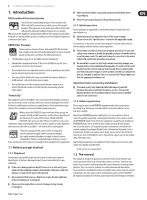
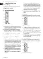
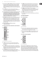
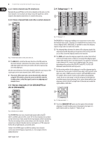
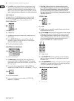
9 EURODESK SX3242FX/SX2442FX User Manual 2.5 Mono out section for subwoofer applications Using this auxiliary mono output you can route the main mix signal to a separate power amp. The tunable low-pass filter allows you to limit the signal content to the low-frequency range to get a perfect subwoofer signal. This signal is mono because very low frequencies disperse quickly, so there would be no benefit to position this signal in the stereo mix. (33) Use this high-precision MAIN fader to control the output level of the main mix. (34) (30) (31) (29) Fig. 2.14: XLR main out connectors (34) The MAIN OUT(puts) are balanced XLR connectors with a nominal operating level of +4 dBu and provide the main mix signal. (36) (35) Fig. 2.15: Main out connectors and main insert Fig. 2.11: Mono out fader and low-pass filter (29) The MONO fader controls the volume of the signal present at the MONO OUT (see (32)). (30) The FREQ control adjusts the cut-off frequency of the low-pass filter (30 to 200 Hz). Frequencies above cut-off are filtered out when activated. (31) Use the LOW PASS FILTER switch to activate the filter function (LED illuminates). (35) The MAIN OUT ¼" TRS connectors outputs also provide the main mix signal. (36) Like the channel inserts, the MAIN INSERT connectors can be used to connect a dynamics processor or equalizer for further processing of the mix signal. The MAIN INSERT refers to the Main Outs (XLR and ¼" TRS connectors), the MONO OUT (see (32)) and, if the MAIN switch in the PHONES/CONTROL ROOM section is pressed, also to the PHONES/CTRL ROOM output (see (46)). (32) (37) (38) fig. 2.12: Mono out connector (32) The MONO OUT connector provides the line-level mono signal for (39) connection to the inputs of a power amp or active speaker. You can also use this output as a monitor bus, e.g. to connect a headphone amplifier. In this case, the signal should of course not be limited by the low-pass filter. 2.6 Main out section (40) (33) Fig. 2.13: Main out fader Fig. 2.16: Level meter (37) The red "+48 V" LED illuminates when phantom power is on. Phantom power is required for the operation of condenser microphones, and can be switched on with the corresponding switch on the rear of the console. (38) The POWER LED is illuminated when the console is switched on. (39) The high-precision level meter accurately indicates the output signal level. For example, when you press the SOLO switch on one of the input channels, its signal level will be displayed here, either pre-fader (PFL) or post-fader (SOLO), depending on the position of the SOLO/ PFL switch (see (40)). In PFL mode only the left display is active, because the PFL signals are mono.
-
 1
1 -
2
-
3
-
 4
4 -
 5
5 -
 6
6 -
 7
7 -
 8
8 -
 9
9 -
 10
10 -
 11
11 -
 12
12 -
 13
13 -
 14
14 -
15
-
16
-
17
-
18
-
19
-
20
 |
 |