Behringer EURODESK SX4882 Manual - Page 8
Inserts, B-channel - user manual
 |
View all Behringer EURODESK SX4882 manuals
Add to My Manuals
Save this manual to your list of manuals |
Page 8 highlights
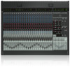
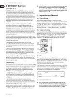
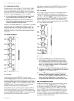
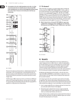
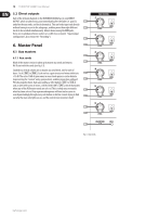
8 EURODESK SX4882 User Manual ◊ An exception to this rule is when laying down voice takes. It is often convenient to have the mic channel(s) routed to alt potential TAKE tracks simultaneously, since you are often dropping in quickly between four or more tracks. It means one less button press each time you switch tracks. 3.7 B-channel The B-channel (fig. 3.6) comprises a secondary channel with its own high and low EQ, pan and level ( P 18 , P 19 , P 20 and P 21 ). The EQ is a replica of the A-channel shelving EQ. The B-channel ALWAYS feeds into the MIX-B stereo bus, but its source can be switched between TAPE, LINE, MIC and A-CHANNEL, depending on how S 1 , S 3 and S 23 are set (see fig. 3.2 and section 3.2). Unusually for an 8-bus console, B-channels also have their own MUTE buttons ( S 22 ). Aux sends 3/4/5/6 may be diverted from the A to the B-channel via S 17 . Therefore, if the B-channel is being used to monitor off-tape, some FX processing e.g. reverb and echo can still be applied. (See section 16.3 "Wet monitoring".) ◊ When B-channel looks at A-channel ( S 23 DOWN), the signal comes A-channel mute switch and pre fader. A modification can convert this PRE stereo aux send to POST fader. (See 23.2 "MIX-B source > post fader".) Fig. 3.6: B-channel Fig. 3.5: Routing The level to the subgroup and main mix buses is ultimately determined by the channel faders. These are designed to give a smooth logarithmic taper of a type more usually associated with the name of some pretty expensive brand ... The low level performance particularly is far smoother than that of a normal "budget" fader. The MUTE button ( S 27 ), like that for SOLO has an LED indicator ( L 27 ) and removes the A-channel signal from all buses, save any auxes set to pre fader. It is ergonomically placed immediately above the fader and engaging MUTE is equivalent to setting a fader level of minus infinity. behringer.com 4. Inserts Insert points are useful for adding dynamic processing or equalization to a channel, subgroup or the mix. Unlike reverbs, etc., which are usually added to the dry signal, dynamic processing is normally applied across an entire signal. Here, an aux send would be inappropriate. Instead the signal is intercepted somewhere along the channel/subgroup/mix, fed through the dynamics processor and/or EQ and then returned to the console at the same point where it left. The insert point is invisible or normalized, until a jack is plugged into it. All subgroups and channels have got insert points, as does the main stereo output. Both SEND and RETURN are accommodated on a single stereo 1/4" jack socket wired tip=send, ring=return. Inserts are always pre fader and also pre EQ / aux sends for channels. Insert points may also be used as pre EQ direct outputs without interrupting the signal flow. This is obvious when looking at the patchbay wiring (section 8, fig. 8.1). If you want to insert a dynamics processor post EQ, the insert point must either be taken from a subgroup, or via a second channel / aux return as follows: 1) Insert a compressor/gate/EQ across a subgroup, and route the channel to be processed (and only that channel) to that subgroup. 2) Alternatively, patch a channel's direct out into a compressor/gate/EQ. Take the output from that compressor/gate/EQ and feed it back into the desk via a secondary input (channel, aux return, etc.). Figure 4.1 illustrates how you might insert into a channel post EQ for mixdown or track-laying (their requirements are different). Mixdown requires one A and one B-channel. Recording requires two A-channels.
-
 1
1 -
2
-
 3
3 -
 4
4 -
 5
5 -
 6
6 -
 7
7 -
 8
8 -
 9
9 -
 10
10 -
 11
11 -
 12
12 -
 13
13 -
14
-
15
-
16
-
17
-
18
-
19
-
20
-
21
-
22
-
23
-
24
-
25
-
26
-
27
-
28
-
29
-
30
-
31
-
32
 |
 |
