Behringer SONIC ULTRAMIZER SU9920 Manual - Page 9
Specifications
 |
View all Behringer SONIC ULTRAMIZER SU9920 manuals
Add to My Manuals
Save this manual to your list of manuals |
Page 9 highlights
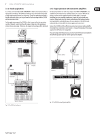
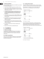
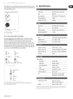
9 SONIC ULTRAMIZER SU9920 User Manual Alternatively, you can use professional XLR cables with an XLR socket on one side and an XLR plug on the other side. This cable connection is the most reliable both electrically and mechanically. 5. Specifications Inputs Balanced use with XLR connectors 21 3 input 1 = ground/shield 2 = hot (+ve) 3 = cold (-ve) 12 3 output For unbalanced use, pin 1 and pin 3 have to be bridged Fig. 4.3: Balanced XLR plug Connections Type Input impedance Nominal input level Maximum input level Outputs Connections Type Output impedance Maximum output level XLR sockets and ¼" stereo jacks Balanced 20 kΩ balanced, 10 kΩ unbalanced +4 dBu +22 dBu XLR sockets and ¼" stereo jacks Servo-balanced 60 Ω balanced, 60 Ω unbalanced +22 dBu 4.2.2 Connection with insert cables Please use standard insert cables equipped with ¼" connectors to connect the SONIC ULTRAMIZER to the insert path of a mixing console. These Y cables have two ¼" TS connectors at one end, and one ¼" TRS connector at the other. Connect the plug marked "Send" to the INPUT L jack on the effects unit. Connect the "Return" plug to the OUTPUT L jack on the device. Connect the TRS connector to the insert jack of the channel strip on the mixing console. Use two insert cables for stereo sub-groups and main-mix inserts. The second cable must be connected to the INPUT/OUTPUT R jacks of the SU9920. Return (out) tip signal Send (in) tip signal Enhancer Section Type PROCESS control LOW CONTOUR control System Data Frequency response Signal-to-noise ratio Distortion (THD + N) Crosstalk 3-band phase delay and dynamic filter max. 12 dBu @ 5 kHz max. 12 dBu @ 50 kHz 25 Hz to 50 kHz, +/-3 dB >95 dB, unweighted, 20 Hz to 20 kHz 0.05% typ. @ +4 dBu, 1 kHz (IN/OUT) >75 dB sleeve ground/shield sleeve ground/shield tip sleeve strain relief clamp tip sleeve strain relief clamp strain relief clamp sleeve ring tip sleeve ground/shield ring return (in) tip send (out) Fig. 4.4: Insert cable with one ¼" TRS (tip-ring-sleeve) jack plug on one end and two ¼" TS (tip-sleevel) jack plugs on the other end. Power Supply Mains Voltage USA/Canada China/Korea Europe/UK/Australia Japan Export model Power consumption Fuse 120 VAC, 60 Hz 220 VAC, 50/60 Hz 230 VAC, 50 Hz 100 VAC, 50-60 Hz 120/230 VAC, 50-60 Hz approx. 12 W 100-120 VAC: T 250 mA, H 250 V 220-240 VAC: T 125 mA, H 250 V Dimensions/Weight Dimensions (H x W x D) Weight approx. 8.5 x 1.8 x 19'' approx. 217 x 44.5 x 483 mm approx. 4.84 lbs / 2.20 kg BEHRINGER is constantly striving to maintain the highest professional standards. As a result of these efforts, modifications may be made from time to time to existing products without prior notice. Specifications and appearance may differ from those listed or illustrated.
-
 1
1 -
2
-
3
-
 4
4 -
 5
5 -
 6
6 -
 7
7 -
 8
8 -
 9
9 -
 10
10
 |
 |
