Behringer UB1222FX-PRO User Manual - Page 11
Graphic 7-band equalizer, 5 Rear view of UB1222FX-PRO
 |
View all Behringer UB1222FX-PRO manuals
Add to My Manuals
Save this manual to your list of manuals |
Page 11 highlights
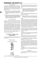
EURORACK UB1222FX-PRO + Connect microphones before you switch on the phantom power supply. Please do not connect microphones to the mixer (or the stagebox/ wallbox) while the phantom power supply is switched on. In addition, the monitor/PA loudspeakers should be muted before you activate the phantom power supply. After switching on, wait approx. one minute to allow for system stabilization. 2.5 Rear view of UB1222FX-PRO LEVEL METER/CLIP The high-precision level meter accurately displays the appropriate signal level. LEVEL SETTING: When recording to a digital device, the recorder’s peak meter should not exceed 0 dB. This is because, unlike analog recordings, slightly excessive levels can create unpleasant digital distortion. When recording to an analog device, the VU meters of the recording machine should reach approx. +3 dB with lowfrequency signals (e.g. kick drum). Due to their inertia VU meters tend to display too low a signal level at frequencies above 1 kHz. This is why, for example, a Hi-Hat should only be driven as far as -10 dB. Snare drums should be driven to approx. 0 dB. + The peak meters of your EURORACK display the level virtually independent of frequency. A recording level of 0 dB is recommended for all signal types. 2.4 Graphic 7-band equalizer Fig. 2.15: The graphic stereo equalizer The graphic stereo equalizer allows you to tailor the sound to the room acoustics. FBQ FEEDBACK DETECTION The switch turns on the FBQ Feedback Detection System. It uses the LEDs in the frequency band faders to indicate the critical frequencies. On a per-need basis, lower the frequency range in question somewhat in order to avoid feedback. The graphic stereo equalizer has to be turned on in order to use this function. + Logically, at least one (ideally several) microphone channels have to be open for feedback to occur at all! Feedback is particularly common when stage monitors (“wedges”) are concerned, because monitors project sound in the direction of microphones. Therefore, you can also use the FBQ Feedback Detection for monitors by placing the equalizer in the monitor bus (see MAIN MIX/MONITOR). EQ IN Use this switch to activate the graphic equalizer. When activated, the fader LEDs will illuminate. MAIN MIX/MONITOR This toggles the graphic equalizer between the main mix and the monitor mix. With the switch up (not depressed), the equalizer is active in stereo on the main mix, and inactive on the monitor mix. When the switch is depressed the equalizer is active in mono on the monitor mix, and inactive on the main mix. Fig. 2.16: Voltage supply and fuse FUSE HOLDER/IEC MAINS RECEPTACLE The console is connected to the mains via the cable supplied, which meets the required safety standards. Blown fuses must only be replaced by fuses of the same type and rating. The mains connection is made via a cable with IEC mains connector. An appropriate mains cable is supplied with the equipment. POWER Use the POWER switch to power up the mixing console. The POWER switch should always be in the “Off” position when you are about to connect your unit to the mains. To disconnect the unit from the mains, pull out the main cord plug. When installing the product, ensure that the plug is easily accessible. If mounting in a rack, ensure that the mains can be easily disconnected by a plug pull or by an all-pole disconnect switch on or near the rack. + Attention: The POWER switch does not fully disconnect the unit from the mains. Unplug the power cord completely when the unit is not used for prolonged periods of time. PHANTOM The PHANTOM switch activates the phantom power supply for the XLR microphone inputs, which is required to operate condenser microphones. The red +48 V LED lights up when phantom power is on. As a rule, dynamic microphones can still be used with phantom power switched on, provided that they are wired in a balanced configuration. In case of doubt, contact the microphone manufacturer! + Connect microphones before you switch on the phantom power supply. Please do not connect microphones to the mixer (or the stagebox/ wallbox) while the phantom power supply is switched on. In addition, the monitor/PA loudspeakers should be muted before you activate the phantom power supply. After switching on, wait approx. one minute to allow for system stabilization. + Caution! You must never use unbalanced XLR connectors (PIN 1 and 3 connected) on the MIC input connectors if you want to use the phantom power supply. SERIAL NUMBER Please note the important information on the serial number given in chapter 1.3.3. 2. CONTROL ELEMENTS AND CONNECTORS 11
-
 1
1 -
2
-
3
-
4
-
5
-
 6
6 -
 7
7 -
 8
8 -
 9
9 -
 10
10 -
 11
11 -
 12
12 -
 13
13 -
 14
14 -
 15
15
 |
 |
