Behringer XENYX 802 User Manual - Page 5
Control elements and connectors - help
 |
View all Behringer XENYX 802 manuals
Add to My Manuals
Save this manual to your list of manuals |
Page 5 highlights
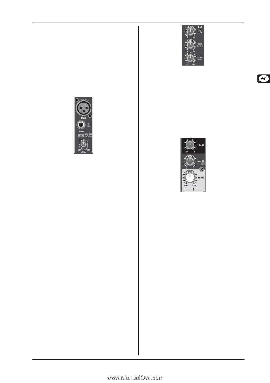
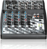
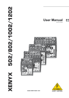
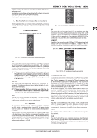
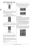
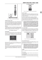
can be found in the support area of our website (http://www. behringer.com). Registering your purchase and equipment with us helps us process your repair claims more quickly and efficiently. Thank you for your cooperation! XENYX 502/802/1002/1202 2. Control elements and connectors This chapter describes the various control elements of your mixing console. All controls, switches and connectors will be discussed in detail. 2.1 Mono channels 2.1.1 Microphone and line inputs Fig. 2.2: The equalizer of the mono input channels EQ The upper (HI) and the lower band (LO) are shelving filters that increase or decrease all frequencies above or below their cut-off frequency. The cut-off frequencies of the upper and lower band are 12 kHz and 80 Hz respectively. The mid band (802/1002/1202) is configured as a peak filter with a center frequency of 2.5 kHz. LOW CUT In addition, the mono channels (1002 and 1202) are equipped with a steep LOW CUT filter (slope at 18 dB/oct., -3 dB at 75 Hz) designed to eliminate unwanted low-frequency signal components. 2.1.3 FX sends, panorama and level adjustment Fig. 2.1: Connectors and controls of mic/line inputs MIC Each mono input channel offers a balanced microphone input via the XLR connector and also features switchable +48 V phantom power supply for condenser microphones. The XENYX preamps provide undistorted and noise-free gain as is typically known only from costly outboard preamps. ++ Please mute your playback system before you activate the phantom power supply to prevent switch-on thumps being directed to your loudspeakers. Please also note the instructions in chapter 2.3.5 "Phantom power and LED displays". LINE IN Each mono input also features a balanced line input on a 1/4" connector. Unbalanced devices (mono jacks) can also be connected to these inputs. ++ Please remember that you can only use either the microphone or the line input of a channel at any one time. You can never use both simultaneously! TRIM Use the TRIM control to adjust the input gain. This control should always be turned fully counterclockwise whenever you connect or disconnect a signal source to one of the inputs. 2.1.2 Equalizer All mono input channels include a 3-band equalizer, except for the 502, which is equipped with a 2-band EQ. All bands provide boost or cut of up to 15 dB. In the central position, the equalizer is inactive. The circuitry of the British EQs is based on the technology used in the best-known top-of-the-line consoles and providing a warm sound without any unwanted side effects. The result are extremely musical equalizers which, unlike simple equalizers, cause no side effects such as phase shifting or bandwidth limitation, even with extreme gain settings of ±15 dB. Fig. 2.3: The FX send/panorama/level controls FX (802/1002/1202 only) FX sends (or AUX sends) enable you to feed signals via a variable control from one or more channels and sum these signals to a bus. The bus appears at the console's FX send output and can be fed from there to an external effects device. The return from the effects unit is then brought back into the console on the aux return connectors (802) or normal channel inputs. Each FX send is mono and features up to +15 dB gain. As the name suggests, the FX sends of the XENYX mixing consoles are intended to drive effects devices (reverb, delay, etc) and are therefore configured post-fader. This means that the mix between dry signal and effect remains at the level determined by the channel's aux send, irrespective of the channel fader setting. If this were not the case, the effects signal of the channel would remain audible even when the fader is lowered to zero. PAN The PAN control determines the position of the channel signal within the stereo image. This control features a constant-power characteristic, which means the signal is always maintained at a constant level, irrespective of position in the stereo panorama. LEVEL The LEVEL control determines the level of the channel signal in the main mix. CLIP The CLIP LED's of the mono channels illuminate when the input signal is driven too high, which could cause distortion. If this happens, use the TRIM control to reduce the preamp level until the LED does not light anymore. Control elements and connectors 5
-
 1
1 -
 2
2 -
 3
3 -
 4
4 -
 5
5 -
 6
6 -
 7
7 -
 8
8 -
 9
9 -
 10
10 -
 11
11
 |
 |