BenQ DCP10 DCP10 User Manual - Page 5
Rear Panel, Left Panel
 |
View all BenQ DCP10 manuals
Add to My Manuals
Save this manual to your list of manuals |
Page 5 highlights
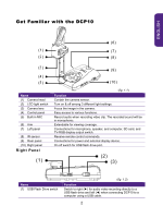
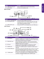
ENGLISH Name (2) USB Flash Drive port (3) Power button Rear Panel Function Insert a USB flash drive for audio video recording. Turn the unit on/standby mode. (1) Name (1) DC12V / LIGHTBOX port (2) DVI-I OUTPUT port (3) RGB OUTPUT port Left Panel (4) (3) (3) (2 ) (fig. 1.3) Function Connect the power adapter into this port. Connect the DCP10 to any display device with DVI cable. If the display device does not support DVI-I, you can only view in Camera and Playback mode. Connect the DCP10 to any display device with RGB cable (5) (6) (2) (1) Name (1) Mini USB port (2) RGB INPUT port (3) MIC port (4) Speaker port (5) RS-232/CVBS port (6) TV-RGB switch (7 ) (fig. 1.4) Function Connect to a USB port of a computer with a USB cable and use DCP10 as a USB Camera or transfer the captured images/videos either from the memory source to computer. Input the signal from a computer or other sources and pass it through to the RGB OUTPUT port only. Connect this port to the RGB/VGA output port of a computer. Connect a 3.5mm plug microphone. The built-in mic will be disabled when an external MIC is connected to this port. Connect to an amplified speaker to playback recorded audio & video clip. Connect the supplied RS-232/CVBS cable into this port. The RCA jack outputs the video signal from the camera to a TV or video equipment. The RS-232 jack is used to connect to computer serial port or to any control panel or for centralized control if desire. TV switch to output display video from RS232/CVBS (via RCA connection), and RGB to RGB and DVI-I OUTPUT ports. 3
-
 1
1 -
 2
2 -
 3
3 -
 4
4 -
 5
5 -
 6
6 -
 7
7 -
 8
8 -
 9
9 -
 10
10 -
 11
11 -
12
-
13
-
14
-
15
-
16
-
17
-
18
-
19
-
20
-
21
-
22
-
23
-
24
-
25
-
26
-
27
-
28
-
29
-
30
-
31
 |
 |
