Biostar 865G MICRO 775 865G Micro 775 bios setup description
Biostar 865G MICRO 775 Manual
 |
View all Biostar 865G MICRO 775 manuals
Add to My Manuals
Save this manual to your list of manuals |
Biostar 865G MICRO 775 manual content summary:
- Biostar 865G MICRO 775 | 865G Micro 775 bios setup description - Page 1
865GMicro 775 BIOS Setup BIOS Setup 1 1 Main Menu 3 2 Standard CMOS Features 6 3 Advanced BIOS Features 9 4 Advanced Chipset Features 15 5 Integrated Peripherals 18 6 Power Management Setup 24 7 PnP/PCI Configurations 28 8 PC Health Status 30 9 Frequency /Voltage Control 32 i - Biostar 865G MICRO 775 | 865G Micro 775 bios setup description - Page 2
865G Micro 775 BIOS Setup Introduction This manual discussed Award™ Setup program built into the ROM BIOS. The Setup program allows users rest of this manual is intended to guide you through the process of configuring your system using Setup. Plug and Play Support These AWARD BIOS supports the Plug - Biostar 865G MICRO 775 | 865G Micro 775 bios setup description - Page 3
865G Micro 775 PCI Bus Support This AWARD BIOS also supports Version 2.1 of the Intel PCI (Peripheral Component Interconnect) local bus specification. DRAM Support DDR DRAM (Double Data Rate Synchronous DRAM) are supported. Supported CPUs This AWARD BIOS supports the Intel Pentium ® 4 CPU. Using - Biostar 865G MICRO 775 | 865G Micro 775 bios setup description - Page 4
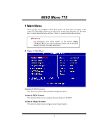
865G Micro 775 1 Main Menu Once you enter Award BIOS™ CMOS Setup Utility, the Main Menu will appear on . 0WARNING The information about BIOS defaults on this manual (Figure 1,2,3,4,5,6,7,8,9) is just only for reference, please refer to the BIOS installed on board, for update information. „ Figure 1. - Biostar 865G MICRO 775 | 865G Micro 775 bios setup description - Page 5
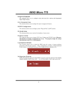
865G Micro 775 Integrated Peripherals This submenu allows you to configure certain IDE hard drive the voltage and clock may cause CPU or M/B damage!) Load Optimized Defaults This selection allows you to reload the BIOS when the system is having problems particularly with the boot sequence. These - Biostar 865G MICRO 775 | 865G Micro 775 bios setup description - Page 6
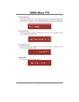
865G Micro 775 Set User Password If the Supervisor Password is not set, then the User Password will function in the same way Abandon all changes made during the current session and exit setup. Confirmation message will be displayed before proceeding. Upgrade BIOS This submenu allows you to upgrade - Biostar 865G MICRO 775 | 865G Micro 775 bios setup description - Page 7
865G Micro 775 2 Standard CMOS Features The items in Standard CMOS Setup Menu are divided into 10 categories. Each category includes no, one or more than one setup - Biostar 865G MICRO 775 | 865G Micro 775 bios setup description - Page 8
865G Micro 775 Main Menu Selections This table shows the selections that you can make on the Main Menu. Item Options Select the type of floppy disk drive installed in your system. Drive B 1.44M, 3.5 in 2.88M, 3.5 in None Video EGA/VGA CGA 40 Select the default video device. CGA 80 MONO 7 - Biostar 865G MICRO 775 | 865G Micro 775 bios setup description - Page 9
865G Micro 775 Item Halt On Base Memory Extended Memory Total Memory Options All Errors No Errors All, but Keyboard All, but Diskette All, but Disk/ Key N/A N/A N/A Description Select the situation in which you want the BIOS to stop the POST process and notify you. Displays the amount of - Biostar 865G MICRO 775 | 865G Micro 775 bios setup description - Page 10
865G Micro 775 3 Advanced BIOS Features „ Figure 3. Advanced BIOS Setup 9 - Biostar 865G MICRO 775 | 865G Micro 775 bios setup description - Page 11
865G Micro 775 Boot Seq & Floppy Setup Hard Disk Boot Priority These BIOS attempt to arrange the Hard Disk boot sequence automatically. This will depend on which Hard Disk is installed. The Choices: Pri. Master, Pri. Slave, Sec. - Biostar 865G MICRO 775 | 865G Micro 775 bios setup description - Page 12
865G Micro 775 First/ Second/ Third/ Boot Other Device These BIOS attempt to load the operating system from the device Report NO FDD for Win95. The Choices: NO (default),Yes. Cache Setup CPU L1&L2 Cache Depending on the CPU/chipset in use, you may be able to increase memory access time with this - Biostar 865G MICRO 775 | 865G Micro 775 bios setup description - Page 13
865G Micro 775 CPU L3 Cache Depending on the CPU/chipset in use, you may be able to increase memory access time with this option. Enabled (default) Enable cache. Disabled Disable cache. CPU Feature Delay Prior to Thermal Set this item to enable the CPU Thermal function to engage after the - Biostar 865G MICRO 775 | 865G Micro 775 bios setup description - Page 14
865G Micro 775 Limit CPU ID Max Val Set limit CPU ID maximun vale to 3, it should be disabled for WinXP. The and an attempt is made to write to the boot sector, BIOS will display a warning message on the screen and sound an alarm beep. Enabled Virus protection is activated. Disabled (default) - Biostar 865G MICRO 775 | 865G Micro 775 bios setup description - Page 15
865G Micro 775 Select if chipset or keyboard controller should control Gate A20. Normal (default), Disabled. MPS Version Control For OS The BIOS supports version 1.1 and 1.4 of the Intel multiprocessor specification. Select version supported by the operation system running on this computer. The - Biostar 865G MICRO 775 | 865G Micro 775 bios setup description - Page 16
865G Micro 775 4 Advanced Chipset Features This submenu allows you to configure the number of clock cycles of CAS latency depends on the DRAM timing. The Choices: By SPD (default), Manual. CAS Latency Time When synchronous DRAM is installed, the number of clock cycles of CAS latency depends on - Biostar 865G MICRO 775 | 865G Micro 775 bios setup description - Page 17
865G Micro 775 DRAM RAS# to CAS# Delay This field let you insert a timing delay any program writes to this memory area, a system error may result. The Choices: Enabled (default), Disabled. Video BIOS Cacheable Select Enabled allows caching of the video BIOS, resulting a better system performance. - Biostar 865G MICRO 775 | 865G Micro 775 bios setup description - Page 18
865G Micro 775 Init Display First This item allows you to decide to active whether PCI Slot or on-chip VGA first. The Choices: PCI Slot (default), Onboard/AGP 17 - Biostar 865G MICRO 775 | 865G Micro 775 bios setup description - Page 19
865G Micro 775 5 Integrated Peripherals „ Figure 5. Integrated Peripherals 18 - Biostar 865G MICRO 775 | 865G Micro 775 bios setup description - Page 20
865G Micro 775 Onboard IDE Device Press Enter to configure the onboard IDE Controllers. IDE HDD Block Mode Block mode is also called block transfer, multiple commands, or multiple sector read / write. If your IDE hard drive supports block mode (most new drives do), select Enabled for automatic - Biostar 865G MICRO 775 | 865G Micro 775 bios setup description - Page 21
865G Micro 775 Primary / Secondary /Master / Slave UDMA Ultra DMA/100 functionality can be implemented if it is supported by the IDE hard drives in your system. As well, your operating environment requires a DMA driver (Windows 95 OSR2 or a third party IDE bus master driver). If your hard drive and - Biostar 865G MICRO 775 | 865G Micro 775 bios setup description - Page 22
865G Micro 775 Onboard Device Press Enter to configure the onboard Device. USB Controller Select enabled/ disabled EHCI controller only. This BIOS itself may/ may not have high speed USB support. If the BIOS has high speed USB support built in, the support will automatically turn on, when high speed - Biostar 865G MICRO 775 | 865G Micro 775 bios setup description - Page 23
865G Micro 775 AC97 Audio This item allows you to decide to enable/ disable to AC97 Audio support. The Choices: Auto (default), Disabled. AC97 Modem This item allows you to decide to enable/ disable to AC97 Modem support. The Choices: Auto (default), Disabled. Onboard PCI LAN This item allows you to - Biostar 865G MICRO 775 | 865G Micro 775 bios setup description - Page 24
865G Micro 775 Onboard Serial Port 2 Select an address and corresponding interrupt for the first and second serial ports The Choices: 2F8/IRQ3 (default), Disabled, Auto, 3F8/IRQ4, - Biostar 865G MICRO 775 | 865G Micro 775 bios setup description - Page 25
865G Micro 775 6 Power Management Setup The Power Management Setup Menu allows you to configure your system to utilize energy conservation and power up/power down features. „ Figure 6. - Biostar 865G MICRO 775 | 865G Micro 775 bios setup description - Page 26
865G Micro 775 HDD Power Down = 15 min Max Saving Maximum power management only available for sl CPU's. Doze Mode = 1 min Standby Mode = 1 min. Suspend Mode = 1 min. HDD Power Down = 1 min. User Defined (default) Allows you to set each mode individually. When not - Biostar 865G MICRO 775 | 865G Micro 775 bios setup description - Page 27
865G Micro 775 Suspend Mode When enabled and after the set time of system inactivity, all devices except the CPU will be shut off. The Choices: Disabled (default), 1Min, 2Min, 4Min, 8Min, 12Min, 20Min, 30Min, 40Min, 1Hour. HDD Power Down When enabled and after the - Biostar 865G MICRO 775 | 865G Micro 775 bios setup description - Page 28
865G Micro 775 The Choices: Disabled (default), Enabled. FDD, COM, LPT Port You can select to enable or disable FDD, COM, and LPT port under this item. The - Biostar 865G MICRO 775 | 865G Micro 775 bios setup description - Page 29
865G Micro 775 7 PnP/PCI Configurations This section describes configuring the PCI bus system. PCI, or Personal Computer Interconnect, is a system which allows I/O devices to operate at speeds nearing the speed of the CPU Reset Configuration Data The system BIOS supports the PnP feature which - Biostar 865G MICRO 775 | 865G Micro 775 bios setup description - Page 30
865G Micro 775 Resources Controlled By By Choosing "Auto(ESCD)" (default), the system BIOS will detect the system resources and automatically assign the relative IRQ and DMA channel for each peripheral.By Choosing "Manual to the ISA bus. The non-VGA ISA graphic controller can then snoop the - Biostar 865G MICRO 775 | 865G Micro 775 bios setup description - Page 31
865G Micro 775 8 PC Health Status „ Figure 8. PC Health Status Shutdown Temperature This item allows you to set up the CPU shutdown Temperature. This item is only effective under Windows 98 ACPI mode. The Choices: 60°C/140°C, 65°C/149°F, 70°C/140°C, Disabled (default). SYS FAN Control - Biostar 865G MICRO 775 | 865G Micro 775 bios setup description - Page 32
865G Micro 775 Start PWM Value When CPU temperature arrives to the set value, the CPU fan will work under Smart Fan Function mode. The range is from 0~127, with an interval of 1. The Choices: 32 (default). Slope PWM Increasing the value of slope PWM will raise the speed of CPU fan. The Choices: 1 - Biostar 865G MICRO 775 | 865G Micro 775 bios setup description - Page 33
865G Micro 775 9 Frequency /Voltage Control „ Figure 9. Frequency Control CPU Clock Ratio The Choices: 8 X (default). Min= 8,Max= 50,Key in a DEC number. Auto Detect PCI Clk This item allows you to enable / disable auto Detect - Biostar 865G MICRO 775 | 865G Micro 775 bios setup description - Page 34
865G Micro 775 CPU Clock This item allows you to select CPU Clock, and CPU over clocking. The Choices: 100 (default). Min= 100,Max= 255,Key in a DEC number. If unfortunately, the system's frequency that you are selected is not
-
 1
1 -
 2
2 -
 3
3 -
 4
4 -
 5
5 -
 6
6 -
 7
7 -
8
-
9
-
10
-
11
-
12
-
13
-
14
-
15
-
16
-
17
-
18
-
19
-
20
-
21
-
22
-
23
-
24
-
25
-
26
-
27
-
28
-
29
-
30
-
31
-
32
-
33
-
34
 |
 |

865GMicro 775 BIOS Setup
i
BIOS Setup
.......................................................................................
1
1 Main Menu
...................................................................................................
3
2 Standard CMOS Features
.............................................................................
6
3 Advanced BIOS Features
.............................................................................
9
4 Advanced Chipset Features
........................................................................
15
5 Integrated Peripherals
.................................................................................
18
6 Power Management Setup
..........................................................................
24
7 PnP/PCI Configurations
..............................................................................
28
8 PC Health Status
.........................................................................................
30
9 Frequency /Voltage Control
.......................................................................
32