Biostar M7NCG 400 M7NCG 400 user's manual
Biostar M7NCG 400 Manual
 |
View all Biostar M7NCG 400 manuals
Add to My Manuals
Save this manual to your list of manuals |
Biostar M7NCG 400 manual content summary:
- Biostar M7NCG 400 | M7NCG 400 user's manual - Page 1
M7NCG 400 FCC if not installed and used in accordance with the instructions, may cause harmful interference to radio communications. There writing. Even thought we have taken every care in the preparation of this user's manual, no guarantee is given as to the correctness of its contents. All - Biostar M7NCG 400 | M7NCG 400 user's manual - Page 2
25 M7NCG 400 Features ...25 Verpackungsinhalt...26 Layout des M7NCG 400 ...27 Installation der CPU ...28 DDR-DIMM-Modules: DIMMB1/DIMMB2/ DIMMA1 29 Jumper, Header, Anschlüsse & Slots 30 FRANÇAIS 37 M7NCG 400 Particularités 37 Dessin d'M7NCG 400 ...39 9TH TOUCHTM IS NICE TOUCH 40 BIOS STAR - Biostar M7NCG 400 | M7NCG 400 user's manual - Page 3
English M7NCG 400 Features CPU - Supports the AMD® Socket462 processor up to XP 3200+. - Running at 200/266/333/400MHz Front Side Bus. Chipset - North Bridge: nFORCE2 Crush 18G IGP Chipset. - South Bridge: MCP Chipset. High Speed 800Mb/s Hyper-Transport interface to the MCP. Main Memory - Supports - Biostar M7NCG 400 | M7NCG 400 user's manual - Page 4
- Supports USB Function. Operating System - Offers the highest performance for MS-DOS, Windows 2000, Windows Me, Windows XP, SCO UNIX etc. Dimensions - Micro ATX Form Factor: 24.4cm X 24.4cm (W X L) Package contents - HDD Cable X 1 - FDD Cable X 1 - Fully Setup Driver CD X 1 - User Manual X 1 - USB - Biostar M7NCG 400 | M7NCG 400 user's manual - Page 5
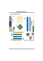
MMootthheerrbbooaarrdd DDeessccrriippttiioonn Layout of M7NCG 400 JKBMS1 JKBV1 1 JUSBLAN1 JCOM1 1 JUSBV2 JPRNT1 1 JCFAN1 FDD1 JATXPWER1 FLOPPY DISK CONN. DIMMB1 DIMMB2 DIMMA1 1 JCLK3 JTV1 24 13 JVGA1 JSPKR1 SP-OUT Winbond I/O GAME Port JLIN1 LINE-IN 5 JMIC1 MIC-IN 1 JGAME1 1 - Biostar M7NCG 400 | M7NCG 400 user's manual - Page 6
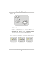
90-degree angle. 2. Locate Pin A in the socket and lock for the white dot or cut edge in the CPU. Match Pin A with the white dot/cut edge then insert the CPU. 3. Press the lever down. Then Put the fan on the CPU and buckle it and put the fan's power port into the JCFAN1, then to - Biostar M7NCG 400 | M7NCG 400 user's manual - Page 7
has to be the combination of DIMMA and DIMMB.) With only one DIMM installed, the memory performs only at 64-bit. DRAM Access Time: 2.5V Unbuffered 128MB/ 256MB/ 512MB/ 1GB DIMM Module (184 pin) DIMM Socket Location DDR Module Total Memory Size (MB) DIMMB1 DIMMB2 DIMMA1 64MB/128MB/256MB/512MB - Biostar M7NCG 400 | M7NCG 400 user's manual - Page 8
, which supports audio, network and modem only. Peripheral Component Interconnect Slots: PCI 1-3 This motherboard is equipped ports. This PCI slot is designated as 32 bits. AGP (Accelerated Graphics Port) Slot: AGP1 Your monitor will attach directly to that video card. This motherboard supports video - Biostar M7NCG 400 | M7NCG 400 user's manual - Page 9
MMootthheerrbbooaarrdd DDeessccrriippttiioonn Wake On LAN Header: JWOL1 Wake up Ground 1 5V_SB JWOL1 Front USB Header: JUSB1/ JUSB2 2 1 JUSB1/2 Pin Assignment Pin Assignment 1 +5V 2 +5V 3 Data (-) 4 Data (-) 5 Data (+) 6 Data (+) 7 Ground 8 Ground 9 Key 10 NA 5V/ 5V_SB Selection - Biostar M7NCG 400 | M7NCG 400 user's manual - Page 10
for USB: JUSBV1/JUSBV2/ (JUSBV4=>optional) JUSBV1/ 2/ 4 Assignment 1 5V Pin 1-2 on 1 Pin 2-3 on 5V Standby Note: 5V Standby only use for S3 Mode. Front Panel Connector: JPANEL1 PWR_LED SLP ON/OFF IR 2 24 1 23 SPK (H+)L(E-)DRST IR SPK HLED RST IR ==> Speaker Conn. ==> Hard Driver LED - Biostar M7NCG 400 | M7NCG 400 user's manual - Page 11
7 Reserved 8 Key 9 LFT Line Out 10 LFT Line Out JF_AUDIO1 only support 2CH. Front Panel Audio Connector/ Jumper Block Jumper Setting 12 3 5 7 4 6 Pin 5 and 6 Pin 9 and 10 9 10 1 3 5 7 9 246 No jumpers 10 installed Configuration Audio line out signals are routed to the back panel - Biostar M7NCG 400 | M7NCG 400 user's manual - Page 12
SSaaffeemmooddeeo(r100MHz) JCLK3 CPU Clock 100MHz Note: When overclock function failed and system is unable to boot-up, please follow the instruction below: 1. Turn off the system. 2. Closed the JCLK3 jumper. 3. Turn on the system. 4. Enter CMOS setup menu and load defaults settings. 5. Turn off - Biostar M7NCG 400 | M7NCG 400 user's manual - Page 13
DDeessccrriippttiioonn CNR Codec Primary/Secondary Selection: J_CODECSEL J_CODECSEL Pin 1-2 1 Pin 2-3 1 Assignment On-board Primary Codec. CNR Primary Codec. Digital Audio Connector: J_SPDIF1 SPDIF_OUT VCC5 GND 1 J_SPDIF1 Audio DJ Header: JDJ1 (optional) 1 5 JDJ1 Pin1 ==> SMBDT Pin2 - Biostar M7NCG 400 | M7NCG 400 user's manual - Page 14
PS/2 LAN(Optional) Mouse JPRNT1 Parallel JGAME1 Game Port PS/2 USB Keyboard COM1 JCOM1 Speaker Line In Mic COM2 Out JPRNT1 Parallel JGAME1 Game Port PS/2 USB Keyboard COM1 JCOM1 VGA1 JVGA1 Speaker Out Line In Mic In The LED indicator for Lan port status: Status Speed Normal - Biostar M7NCG 400 | M7NCG 400 user's manual - Page 15
M7NCG 400 CPU - Soporta procesador AMD® Zócalo 462 de hasta XP 3200+. - Corriendo a 200/266/333/400MHz FSB. Chipset - North Bridge: nFORCE2 - Realtek 8801BL. - Soporta 2 puertos con transferencia de hasta 400Mbps. Audio - Interface AC97 2.2. - PC99 complaint. - Soports 6 canales. - S/PDIF Out. TV - Biostar M7NCG 400 | M7NCG 400 user's manual - Page 16
rendimiento en MS-DOS, Windows 2000, Windows Me, Windows XP, SCO UNIX etc. Dimensión - Factor de Forma Micro ATX: 24.4cm X 24.4cm (W X L) Contenido del Paquete - Cable HDD X 1 - Cable FDD X 1 - Configuración Completa del Driver CD X 1 - Manual del Usuario X 1 - Cable USB X 2 (opcional) - Cable SPDIF - Biostar M7NCG 400 | M7NCG 400 user's manual - Page 17
MMootthheerrbbooaarrdd DDeessccrriippttiioonn Disposición del M7NCG 400 JKBMS1 JKBV1 1 JUSBLAN1 JCOM1 1 JUSBV2 JPRNT1 1 JCFAN1 FDD1 JATXPWER1 FLOPPY DISK CONN. DIMMB1 DIMMB2 DIMMA1 1 JCLK3 JTV1 24 13 JVGA1 JSPKR1 SP-OUT Winbond I/O GAME Port JLIN1 LINE-IN 5 JMIC1 MIC-IN 1 JGAME1 - Biostar M7NCG 400 | M7NCG 400 user's manual - Page 18
contacto A del zócalo y busque el punto blanco o corte el borde en la CPU. Empareje el contacto A con el punto blanco/ corte del borde, luego inserte la CPU. 3. Presione la palanca para abajo. Ponga el ventilador en la CPU y abróchelo. Luego ponga el puerto de corriente del ventilador en el JCFAN1 - Biostar M7NCG 400 | M7NCG 400 user's manual - Page 19
MMootthheerrbbooaarrdd DDeessccrriippttiioonn Módulos DDR DIMM: DIMMB1/DIMMB2/ DIMMA1 Para un alto funcionamiento, Dual-channel DDR (128-bit), por lo menos 2 o más módulos DIMM debe ser instalado. (Tiene que ser la combinación del DIMMA y DIMMB.) Con solamente un DIMM instalado, la memoria funciona - Biostar M7NCG 400 | M7NCG 400 user's manual - Page 20
, y define una tarjeta hardware escalable de interface en el que soporta audio, red y módem. Ranura de Interconexión del Componente Periférico: PCI Su monitor se fijará directamente a la tarjeta de video. Ésta placa madre soporta tarjetas de video para ranuras PCI, y también está equipado con - Biostar M7NCG 400 | M7NCG 400 user's manual - Page 21
MMootthheerrbbooaarrdd DDeessccrriippttiioonn Cabezal Wake On LAN: JWOL1 Wake up Tierra 1 5V_SB JWOL1 Cabezal Frontal USB: JUSB1/ JUSB2 2 1 JUSB1/2 Contactos Asignacion 1 +5V 3 Data (-) 5 Data (+) 7 Tierra 9 Key Contactos 2 4 6 8 10 Asignacion +5V Data (-) Data (+) Tierra NA - Biostar M7NCG 400 | M7NCG 400 user's manual - Page 22
MMootthheerrbbooaarrdd DDeessccrriippttiioonn 5V/ 5V_SB Selección para USB: JUSBV1/JUSBV2/ (JUSBV4=>opcional) JUSBV1/ 2/ 4 Asignacion 1 Contactos ON/ OFF ==> Boton de Encendido Subsistema de Audio: JF_AUDIO1/ JCDIN1 2 1 1 JF_AUDIO1 JCDIN1 (Cabezal de Audio Frontal) (Cabezal de Entrada de - Biostar M7NCG 400 | M7NCG 400 user's manual - Page 23
Audio RT Salida de Linea Key LFT Salida de Linea JF_AUDIO1 only support 2CH. Conector del Panel Frontal de Audio/ Jumper Block Jumper Setting de linea del Audio y la se~nal del entrada del mic estan disponibles desde el conector de Audio del panel frontal. Clear CMOS Jumper: JCMOS JCMOS - Biostar M7NCG 400 | M7NCG 400 user's manual - Page 24
la contrase~na deseada o borre datos CMOS Selección de Frecuencia: JCLK3 Open==> MUsoedrompoadrae el Usuario (Default) 1 ((D1e3f3a/u1lt6)6/ 200 MHz) JCLK3 Close==> SMafoedmo oSdaefeo(r100MHz) CPU Clock 100MHz Nota: Cuando la función del overclock falla y el sistema no pueda encenderse - Biostar M7NCG 400 | M7NCG 400 user's manual - Page 25
Codec Primario 1 1-2 integrado en la placa madre. Contacto CNR Codec Primario. 1 2-3 Conector Digital de Audio: J_SPDIF1 SPDIF_OUT VCC5 GND 1 J_SPDIF1 Cabezal de Audio DJ: JDJ1 (opcional) 1 5 JDJ1 Contacto1 ==> SMBDT Contacto2 ==> SMBCK Contacto3 ==> -INTR_B Contacto4 ==> NC Contacto5 - Biostar M7NCG 400 | M7NCG 400 user's manual - Page 26
Entrada de Linea Salida del Entrada de Altavoz Mic JKBMS1 JUSBLAN1 Raton LAN(Opcional) PS/2 JPRNT1 Paralelo JGAME1 Puerto de Juego Teclado PS/2 USB COM1 JCOM1 COM2 (opcional) JCOM2 (opcional) Salida del Entrada Entrada de Altavoz de Linea Mic Estado del Indicador LED del LAN: Estado - Biostar M7NCG 400 | M7NCG 400 user's manual - Page 27
M7NCG 400 Features CPU - Unterstützung für AMD Prozessor(Sockel462 ) bis zu XP 3200+. - FSB mit 200/266/333/400MHz.. Chipsatz - Northbridge: nFORCE2 8801Bl mit drei 1394 Anschlüssen unterstützt bis zu 400Mbit/s Transferrate. Audio - AC97-2.2-Interface. - PC99 kompatibel. - Unterstützung für 6-Kanal. - Biostar M7NCG 400 | M7NCG 400 user's manual - Page 28
.0-Ports. (hintenX4, vornX2) - Unterstützung für S/PDIF Ausgabe Anschluss. BIOS - Unterstützung für AWARD legal Bios. - Unterstützung für APM1.2. - Unterstützung für ACPI. - Unterstützung für USB Function. Operating System - Unterstützung für die am meisten verbreiteten Betriebsysteme wie Windows - Biostar M7NCG 400 | M7NCG 400 user's manual - Page 29
MMootthheerrbbooaarrdd DDeessccrriippttiioonn Layout des M7NCG 400 JKBMS1 JKBV1 1 JUSBLAN1 JCOM1 1 JUSBV2 JPRNT1 1 JCFAN1 FDD1 JATXPWER1 FLOPPY DISK CONN. DIMMB1 DIMMB2 DIMMA1 1 JCLK3 JTV1 24 13 JVGA1 JSPKR1 SP-OUT Winbond I/O GAME Port JLIN1 LINE-IN 5 JMIC1 MIC-IN 1 JGAME1 1 - Biostar M7NCG 400 | M7NCG 400 user's manual - Page 30
Sockel und neigen Sie ihn um 90-Grad nach oben. 2. Suchen Sie Pin A im Sockel und den weißen Punkt oder die Abschnittkante in der CPU. Passen Sie Pin A mit dem weißen Punkt/der Abschnittkante zusammen und legen Sie danach die CPU ein. 3. Drücken Sie den Hebel nach unten. Befestigen Sie danach - Biostar M7NCG 400 | M7NCG 400 user's manual - Page 31
werden.) DRAM Zugriffszeit: 2.5V unbuffered DDR 200/266/333 MHz Typen erfordert. DRAM Typen: 64MB/ 128MB/ 256MB/ 512MB/ 1GB DIMM-Module (184 pin) DIMM-Sockel Standort DDR-Module Speichergröße (MB) DIMMB1 DIMMB2 DIMMA1 64MB/128MB/256MB/512MB/1GB *1 64MB/128MB/256MB/512MB/1GB *1 maximal 3GB - Biostar M7NCG 400 | M7NCG 400 user's manual - Page 32
, welche nur Audio, Netzwerk und Modem unterstützt. Peripheral Component Interconnect Slots: PCI 1-3 Dieses Motherboard ist mit 3 32 bits vorgesehen. Accelerated Graphics Port Slot: AGP1 Ihr Monitor wird direkt an die Grafikkarte angeschlossen. Dieses Motherboard unterstützt Grafikkarten für PCI- - Biostar M7NCG 400 | M7NCG 400 user's manual - Page 33
4 5 B+ 6 7 +12V 8 9 KEY 10 AGND B+12V GND 5V/ 5V_SB Auswahl für USB: JUSBV1/JUSBV2/ (JUSBV4=>optional) JUSBV1/ 2/ 4 Beschreibung 1 5V Pin 1-2 geschlossen 1 5dVei dreieserrevsieerrvteie5rtVe SSppaannnnuunngg Pin 2-3 geschlossen Anmerkung: Die 5V reservierte Spannung für S3 Modus. 31 - Biostar M7NCG 400 | M7NCG 400 user's manual - Page 34
. SLP ==> Sleep-Taste PWR_LED ==> Stromanzeige EIN/ AUS ==> Ein-/ Ausschalttaste Audio Subsystem: JF_AUDIO1/ JCDIN1 2 1 1 JFJA_AUUDDIOIO11 JCDIN1 (Front Audio Header) (CD-ROM Audio-In Header) 22 10 1 9 Pin Beschreibung 1 Mic-In 3 Mic Power 5 RT Line-Out 7 Reserviert - Biostar M7NCG 400 | M7NCG 400 user's manual - Page 35
und Mic-In-Singals sind verfugbar Kein Jumper fur Audio-Anschlusse an der Vorderseite. 10 installieren Clear CMOS Jumper: JCMOS JCMOS1 Pin 1-2 geschlossen 1 Pin 2-3 geschlossen 1 Beschreibung Normale Operation (Default) CMOS-Daten loschen AC Stromstecker ausziehen JCMOS1 Pin2-3 geschlossen 15 - Biostar M7NCG 400 | M7NCG 400 user's manual - Page 36
. 4. Betreten Sie "CMOS Setup Menü" und wählen sie Default-Setting. 5. Ausschalten Sie den AC-Netzstecker wieder. 6. Lassen Sie Pin 1-2 von JCLK3 geö CNR-Codec: J_CODECSEL J_CODECSEL Pin 1-2 1 Pin 2-3 1 Beschreibung Onboard-Prim.a.rCodec CNR-Prima..r-Codec Digital-Audio-Anschluss: J_SPDIF1 34 - Biostar M7NCG 400 | M7NCG 400 user's manual - Page 37
MMootthheerrbbooaarrdd DDeessccrriippttiioonn 5V/ 5V_SB Auswahl für Tastatur: JKBV1 JKBV1 1 Pin 1-2 geschlossen Beschreibung 5V 1 die reservierte 5V Spannung Pin 2-3 geschlossen Anmerkung: Die 5V reservierte Spannung für S3 Modus. Audio DJ Header: JDJ1 (optional) 1 5 JDJ1 Pin1 ==> SMBDT - Biostar M7NCG 400 | M7NCG 400 user's manual - Page 38
LAN PS/2 (Optional) Maus JPRNT1 Parallel JGAME1 Game-Port PS/2 USB Tastatur COM1 JCOM1 COM2 (optional) JCOM2 (optional) Speaker Mic Out In Line In Die Signallampe für Lan-Port Status: Status Geschwindigkeit 10Mbps 100Mbps Normal Download Lampe von rechts: grün Lampe von links: kein - Biostar M7NCG 400 | M7NCG 400 user's manual - Page 39
M7NCG 400 Particularités CPU - Soutient le processeur d'AMD ® Socket462 jusqu'à XP 3200 +. - Dirigeant à Autobus de Côté 200/266/333MHz de Devant. Chipset - Pont du Nord : nFORCE2 AGP3.0 8X interface à 533Mb/s. * Supports AGP 4X, 8X. À bord IDE - ports avec le taux de transfert jusqu'à 400Mbps. Audio - Biostar M7NCG 400 | M7NCG 400 user's manual - Page 40
d'USB2.0 en arrière et 4 ports d'USB2.0 en avant. - Soutient S/PDIF Out connecteur. BIOS - ACCORDENT le BIOS légal. - Soutient APM1.2. - Soutient ACPI. - Soutient la Fonction d'USB. Système de Fonctionnement - Offre l'exécution(performance) la plus haute pour MS-DOS, Windows 2000, des Fenêtres Moi - Biostar M7NCG 400 | M7NCG 400 user's manual - Page 41
MMootthheerrbbooaarrdd DDeessccrriippttiioonn Dessin d'M7NCG 400 JKBMS1 JKBV1 1 JUSBLAN1 JCOM1 1 JUSBV2 JPRNT1 1 JCFAN1 FDD1 J AT X P W E R 1 GAME Port DIMMB1 DIMMB2 DIMMA1 1 JCLK3 JVGA1 JSPKR1 SP-OUT Winbond I/O JLIN1 LINE-IN 5 JMIC1 MIC-IN 1 JGAME1 1 JDJ1 JNFAN1 Lan Chip 9 1 10 - Biostar M7NCG 400 | M7NCG 400 user's manual - Page 42
[9th Touch] means users could enjoy the speed, safety & convenience when respective booting requirement. The easiest way is just to touch 「F9」 function key during booting procedure to choose any device you like to boot for the system. Forget about entering CMOS, rebooting activities. In addition - Biostar M7NCG 400 | M7NCG 400 user's manual - Page 43
. Second, use and maybe download the flash utility to update the BIOS. Unfortunately, there is no DOS support under WindowsR XP. Moreover, it takes time to prepare the right flash utility and make a Bootable Floppy Disk if necessary. BIOSTAR's [FLASHER™] technology integrates flash utility - Biostar M7NCG 400 | M7NCG 400 user's manual - Page 44
MMootthheerrbbooaarrdd DDeessccrriippttiioonn Figure 1 6. Press " Arrow Up/Down " key to choose BIOS file, refer to Figure 2 Figure 2 7. Press [Enter] to load the BIOS from the floppy disk, refer to Figure 3. 42 - Biostar M7NCG 400 | M7NCG 400 user's manual - Page 45
MMootthheerrbbooaarrdd DDeessccrriippttiioonn Figure 3 8. At the prompt "Are you sure to flash (Y/N) ", press [Y] to flash BIOS or [N] to cancel the flashing process, refer to Figure 4. Figure 4 8. After pressing [Y], the flash starts to process, refer to Figure 5. 43 - Biostar M7NCG 400 | M7NCG 400 user's manual - Page 46
MMootthheerrbbooaarrdd DDeessccrriippttiioonn 10. A message " Flash done, Restart System (Y/N) " will appear if the system was successfully updated the BIOS, refer to Figure 6. Figure 6 11. Press [Enter], then the flashing is done! 44 - Biostar M7NCG 400 | M7NCG 400 user's manual - Page 47
overclocking, the system can be at a vulnerable state. Therefore, the BIOSTAR Watchdog Technology was designed to protect your PC under dangerous over-clock situations. Any over-clocking that reaches the threshold settings, the Watchdog Technology will disable your system from rebooting in the BIOS - Biostar M7NCG 400 | M7NCG 400 user's manual - Page 48
. PROBABLE SOLUTION Screen message says "Invalid Configuration" or * Review system's equipment . Make sure "CMOS Failure." correct information is in setup. PROBABLE SOLUTION Cannot boot system after installing second hard * Set master/slave jumpers correctly. drive. * Run SETUP program and - Biostar M7NCG 400 | M7NCG 400 user's manual - Page 49
disco del controlador. Asegúrese de que ambos lados estén enchufados con seguridad; controle el tipo de disco en la configuración estándar CMOS. * Copiando el disco rígido es extremadamente importante. Todos los discos rígidos son capaces de dañarse en cualquier momento. CAUSA PROBABLE SOLUCI - Biostar M7NCG 400 | M7NCG 400 user's manual - Page 50
Festplatten-Controller. Versichern Sie sich, dass beide Enden richtig angebracht sind; überprüfen Sie den Laufwerktyp in der standardmäßigen CMOS-Einrichtung. * Ein Backup der Festplatte ist sehr wichtig. Alle Festplatten können irgendwann beschädigt werden. MÖGLICHE URSACHE LÖSUNG Das System - Biostar M7NCG 400 | M7NCG 400 user's manual - Page 51
08/26/2003 49
-
 1
1 -
 2
2 -
 3
3 -
 4
4 -
 5
5 -
 6
6 -
 7
7 -
8
-
9
-
10
-
11
-
12
-
13
-
14
-
15
-
16
-
17
-
18
-
19
-
20
-
21
-
22
-
23
-
24
-
25
-
26
-
27
-
28
-
29
-
30
-
31
-
32
-
33
-
34
-
35
-
36
-
37
-
38
-
39
-
40
-
41
-
42
-
43
-
44
-
45
-
46
-
47
-
48
-
49
-
50
-
51
 |
 |

M
M
7
7
N
N
C
C
G
G
4
4
0
0
0
0
i
FCC Statement and Copyright
This equipment has been tested and found to comply with the limits of a
Class B digital device, pursuant to Part 15 of the FCC Rules. These limits
are
designed
to
provide
reasonable
protection
against
harmful
interference in a residential installation. This equipment generates, uses
and can radiate radio frequency energy and, if not installed and used in
accordance with the instructions, may cause harmful interference to radio
communications. There is no guarantee that interference will not occur in
a particular installation.
The vendor makes no representations or warranties with respect to the
contents here of and specially disclaims any implied warranties of
merchantability or fitness for any purpose. Since our products are under
continual improvement, we reserve the right to make changes without
notice.
The material in this manual is the intellectual property of the vendor.
Further the vendor reserves the right to revise this publication and to
make changes to its contents without obligation to notify any party
beforehand. Duplication of this publication, in part or in whole, is not
allowed without first obtaining the vendor’s approval in writing. Even
thought we have taken every care in the preparation of this user’s manual,
no guarantee is given as to the correctness of its contents.
All the brand and product names are the property of their respective
owners.