Biostar TFORCE4 U TForce4 U user's manual
Biostar TFORCE4 U Manual
 |
View all Biostar TFORCE4 U manuals
Add to My Manuals
Save this manual to your list of manuals |
Biostar TFORCE4 U manual content summary:
- Biostar TFORCE4 U | TForce4 U user's manual - Page 1
Biostar T-Series TForce4/ TForce4 U not installed and used in accordance with the instructions, may cause harmful interference to radio communications. 1 HDD Cable x 1 User's Manual x 1 Overclock Guide x 1 Serial ATA Cable x 2 Fully Setup Driver CD x 1 Rear I/O Panel for ATX Case x 1 SPDIF Cable x - Biostar TFORCE4 U | TForce4 U user's manual - Page 2
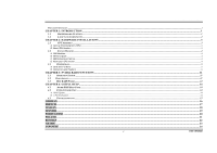
Biostar T-Series TForce4/ TForce4 U PACKAGE CHECKLIST ...I CHAPTER 1: INTRODUCTION ...1 1.1 MOTHERBOARD FEATURES ...1 1.2 LAYOUT AND COMPONENTS ...2 CHAPTER 2: HARDWARE INSTALLATIONS ...3 2.1 CPU ASSEMBLY ...3 A. Central Processing Unit (CPU) ...3 B. About FAN Headers ...3 2.2 SYSTEM - Biostar TFORCE4 U | TForce4 U user's manual - Page 3
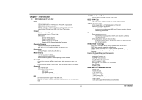
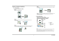
1.1 MOTHERBOARD FEATURES CPU Supports Socket 939. Supports AMD Athlon 64 FX / Athlon 64 /Athlon 64 X2 processors. Supports AMD Sempron processor. AMD 64 architecture enables simultaneous 32 and 64 bit computing. Supports HyperTransport and AMD Cool'n'Quiet Technology. Chipset NVIDIA nForce4 for - Biostar TFORCE4 U | TForce4 U user's manual - Page 4
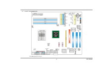
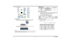
Biostar T-Series 1.2 LAYOUT AND COMPONENTS JATXPWR1 JDDR_0V>3V JCFAN1 DIMM3 DIMM1 DIMM4 DIMM2 Socket 939 JNBFAN1 nForce4 or nForce4 Ultra IDE2 IDE1 LED_D1 LED_D2 LED_DIMM LED_5SB FDD1 TForce4/ TForce4 U JSATA4 JSATA3 JSATA2 JSATA1 JCMOS1 JUSBV1 JUSB3 JUSB2 JUSB1 JCI1 JSFAN1 BAT1 RSTSW PWRSW - Biostar TFORCE4 U | TForce4 U user's manual - Page 5
Biostar T-Series Chapter 2: Hardware Installations 2.1 CPU ASSEMBLY A. Central Processing Unit (CPU) Step 1: Remove the socket protection cap. Step 2: Pull the socket locking lever out from the socket and then raise the lever up to a 90-degree angle. Step 3: Look for the triangular cut edge on - Biostar TFORCE4 U | TForce4 U user's manual - Page 6
out vertically. TForce4/ TForce4 U B. Memory Space DIMM Socket Location DIMM1 DIMM2 DIMM3 DIMM4 DDR Module 128MB/256MB/512MB/1GB *1 128MB/256MB/512MB/1GB *1 128MB/256MB/512MB/1GB *1 128MB/256MB/512MB/1GB *1 Total Memory Size Max is 4 GB. C. DDR Installation Notice For AMD K8 939 CPU launched - Biostar TFORCE4 U | TForce4 U user's manual - Page 7
Biostar T-Series 2.3 PERIPHERALS A. Card and I/O Slots: Floppy Disk Connector: FDD1 The motherboard provides a standard floppy disk connector that supports 360K, 720K, 1.2M, 1.44M and 2.88M floppy disk types. This connector supports the provided floppy drive ribbon cables. TForce4/ TForce4 U - Biostar TFORCE4 U | TForce4 U user's manual - Page 8
Biostar T-Series Xtreme Graphics Port Slot: XGP1 This XGP (Xtreme Graphics Port) slot is a special design that only supports compatible AGP VGA cards. To install the system with an add-on AGP VGA card, please make sure to install the driver of add-on AGP VGA card before onboard VGA driver - Biostar TFORCE4 U | TForce4 U user's manual - Page 9
Biostar T-Series CD-ROM Audio-in Connector: JCDIN1 This connector allows user to connect the audio JUSBV1 Note: In order to support this function "Power-on system 31 Codec BIOS 7 TForce4/ TForce4 U Headers for USB Pin 2-3 Close Note: In order to support this function "Power-on system via keyboard - Biostar TFORCE4 U | TForce4 U user's manual - Page 10
Biostar T-Series Digital Audio-out Connector: JSPDIF_OUT This connector allows users to connect the PCI bracket SPDIF output header. Pin Assignment 1 +5V 2 SPDIF OUT 3 Ground JSPDIF_OUT Codec BIOS 3 1 Front Panel Audio-out Header: JAUDIO2 This connector will allow user to connect with the - Biostar TFORCE4 U | TForce4 U user's manual - Page 11
record to the CMOS and show the message on next boot-up. Pin Assignment 1 Case open signal 2 Ground JCI1 12 Codec BIOS Serial ATA Connectors: JSATA1~JSATA4 The motherboard has an SATA Controller in nForce4 CK8-04 and CK8-04 Ultra with 4 channels SATA interface, it satisfies the SATA 1.0 with - Biostar TFORCE4 U | TForce4 U user's manual - Page 12
OFF ON VGA Error OFF OFF CPU / Chipset Error LED_DIMM: This LED indicates the voltage of memory is activated normally. LED_5SB: This LED indicates the system is ready for Power-on. PWRSW: This is an on-board Power Switch button. RSTSW: This is an on-board Reset button. 10 User's Manual - Biostar TFORCE4 U | TForce4 U user's manual - Page 13
't be adjusted under COMS setup. 3. Before setting memory voltage overclocking, please ensure that your DDR supports up to 3V. (Consulting your DDR supplier) TForce4/ TForce4 U Chapter 3: NVIDIA RAID Functions 3.1 OPERATION SYSTEM Supports Windows XP Home/Professional Edition, and Windows 2000 - Biostar TFORCE4 U | TForce4 U user's manual - Page 14
Biostar T-Series the array fails, all data is lost. Fault Tolerance: No. TForce4/ TForce4 U RAID 1: Every read and write is actually carried out in parallel failure. RAID techniques can be applied for high-availability solutions, or as a form of automatic backup that eliminates tedious manual - Biostar TFORCE4 U | TForce4 U user's manual - Page 15
Biostar T-Series RAID 4 Block 6 Block 1 Block 3 Block 5 Block 2 Block 4 Block 6 TForce4/ TForce4 U Spanning (JBOD): JBOD stands for "Just a Bunch of Disks". Each drive Driver CD, or go to http://www.nvidia.com/page/pg_20011106217193.html to download NVIDIA nForce Tutorial Flash. 13 User's Manual - Biostar TFORCE4 U | TForce4 U user's manual - Page 16
Biostar T-Series CHAPTER 4: USEFUL HELP 4.1 AWARD BIOS BEEP CODE Beep Sound Meaning One long beep followed by two short beeps Video card not found or video card memory bad High-low siren sound CPU overheated System will shut down automatically One Short beep when system boots-up No error - Biostar TFORCE4 U | TForce4 U user's manual - Page 17
Biostar T-Series 4.3 TROUBLESHOOTING Problem Solution 1. No power to the system at all 1. Make sure power cable is securely Power light don't illuminate, fan plugged in. inside power supply does not 2. Replace cable. turn on. 3. Contact technical support. 2. Indicator light on - Biostar TFORCE4 U | TForce4 U user's manual - Page 18
HyperTransport™- ud AMD Cool'n'Quiet™-Technologie. Chipsatz NVIDIA nForce4 (TForce4). NVIDIA nForce4 Ultra (TForce4 Ultra). Unterstützung: Unterstützt NVIDIA Firewall. Unterstützt Gigabit Ethernet. Unterstützt NVIDIA nTune Utility. Unterstützt NVIDIA Secure Networking Processor - Biostar TFORCE4 U | TForce4 U user's manual - Page 19
socket 939. Supporte les processeurs AMD Athlon 64 FX / Athlon 64 /Athlon 64 X2. Prise en charge des processeurs AMD Sempron. Architecture AMD 64 activant des operations 32 et 64 bits. Supporte les technologies HyperTransport™ et AMD Cool'n'Quiet™. Chipset NVIDIA nForce4 (TForce4). NVIDIA nForce4 - Biostar TFORCE4 U | TForce4 U user's manual - Page 20
CPU Supporto di Socket 939. Supporto di processori AMD Athlon 64 FX / Athlon 64 / Athlon 64 X2. Supporto processore AMD Sempron. L'architettura AMD 64 abilita la computazione simultanea 32 e 64 bit. Supporto delle tecnologie HyperTransport™ e AMD Cool'n'Quiet™. Chipset NVIDIA nForce4 (TForce4 - Biostar TFORCE4 U | TForce4 U user's manual - Page 21
Biostar T-Series Spanish Procesador Soporta el Socket 939. Supporta los procesadores AMD Athlon 64 FX / Athlon 64 /Athlon 64 X2. Compatible con el procesador AMD Sempron. La arquitectura AMD 64 permite computación de 32 bits y 64 bits de manera simultánea. Suporta las tecnologías HyperTransport™ y - Biostar TFORCE4 U | TForce4 U user's manual - Page 22
CPU Suporta o socket 939. Suporta processadores AMD Athlon 64 FX / Athlon 64 / Athlon 64 X2. Suporta um processador AMD Sempron. A arquitectura AMD 64 permite uma computação de 32 e 64 bits em simultâneo. Suporta a tecnologia HyperTransport™ e AMD Cool'n'Quiet™. Chipset NVIDIA nForce4 (TForce4 - Biostar TFORCE4 U | TForce4 U user's manual - Page 23
Socket 939. Obsługa procesorów AMD Athlon 64 FX / Athlon 64 / Athlon 64 X2. Obsługa procesorów AMD Sempron Architektura AMD 64 umożliwiająca jednoczesne przetwarzanie 32 i 64 bitowe. Obsługa technologii HyperTransport™ oraz AMD Cool'n'Quiet™. Chipset NVIDIA nForce4 (TForce4). NVIDIA nForce4 Ultra - Biostar TFORCE4 U | TForce4 U user's manual - Page 24
Biostar T-Series Russian CPU 939 AMD Athlon 64 FX, Athlon 64, Athlon 64 X2 AMD Sempron AMD 64 32 64 HyperTransport™ и AMD Cool'n'Quiet™ NVIDIA nForce4 (TForce4). NVIDIA nForce4 Ultra (TForce4 Ultra). NVIDIA. Gigabit Ethernet. NVIDIA nTune. NVIDIA Secure - Biostar TFORCE4 U | TForce4 U user's manual - Page 25
Biostar T-Series Arabic CPU 939 Athlon 64 X2 / Athlon 64 / AMD Athlon 64 FX AMD Sempron processor AMD 64 32و 64 HyperTransport AMD Cool'n'Quiet NVIDIA nForce4 (TForce4). NVIDIA nForce4 Ultra (TForce4 Ultra). NVIDIA Gigabit Ethernet - Biostar TFORCE4 U | TForce4 U user's manual - Page 26
Biostar T-Series Japanese CPU Socket 939 AMD Athlon 64 FX / Athlon 64 / Athlon 64 X2 AMD Sempron AMD 64 32 64 HyperTransport AMD Cool'n'Quiet NVIDIA nForce4 (TForce4). - NVIDIA - Gigabit - NVIDIA nTune - NVIDIA Windows 2000、Windows XP Windows 98SE と
-
 1
1 -
 2
2 -
 3
3 -
 4
4 -
 5
5 -
 6
6 -
 7
7 -
8
-
9
-
10
-
11
-
12
-
13
-
14
-
15
-
16
-
17
-
18
-
19
-
20
-
21
-
22
-
23
-
24
-
25
-
26
 |
 |
Biostar T-Series
TForce4/ TForce4 U
User’s Manual
i
FCC Information and Copyright
This equipment has been tested and found to comply with the limits of a Class B digital device, pursuant to Part 15 of the FCC Rules. These limits are designed to provide
reasonable protection against harmful interference in a residential installation. This equipment generates, uses and can radiate radio frequency energy and, if not installed
and used in accordance with the instructions, may cause harmful interference to radio communications. There is no guarantee that interference will not occur in a particular
installation.
The vendor makes no representations or warranties with respect to the contents here and specially disclaims any implied warranties of merchantability or fitness for any
purpose. Further the vendor reserves the right to revise this publication and to make changes to the contents here without obligation to notify any party beforehand.
Duplication of this publication, in part or in whole, is not allowed without first obtaining the vendor’s approval in writing.
The content of this user’s manual is subject to be changed without notice and we will not be responsible for any mistakes found in this user’s manual. All the brand and product
names are trademarks of their respective companies.
P
ACKAGE
C
HECKLIST
FDD Cable x 1
HDD Cable x 1
User’s Manual x 1
Overclock Guide x 1
Serial ATA Cable x 2
Fully Setup Driver CD x 1
Rear I/O Panel for ATX Case x 1
SPDIF Cable x 1 (optional)
USB 2.0 Cable x 1 (optional)
IEEE 1394A Cable x 1 (optional)