Biostar TFORCE4 U TForce4 U user's manual - Page 7
A. Card and I/O Slots - u motherboard
 |
View all Biostar TFORCE4 U manuals
Add to My Manuals
Save this manual to your list of manuals |
Page 7 highlights
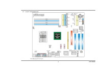
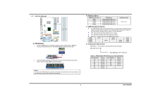
Biostar T-Series 2.3 PERIPHERALS A. Card and I/O Slots: Floppy Disk Connector: FDD1 The motherboard provides a standard floppy disk connector that supports 360K, 720K, 1.2M, 1.44M and 2.88M floppy disk types. This connector supports the provided floppy drive ribbon cables. TForce4/ TForce4 U Peripheral Component Interconnect Slots: PCI1~PCI3 This motherboard is equipped with 3 standard PCI slots. PCI stands for Peripheral Component Interconnect, and it is a bus standard for expansion cards. This PCI slot is designated as 32 bits. 2 34 Codec BIOS 1 33 Hard Disk Connectors: IDE1/IDE2 The motherboard has two 32-bit Enhanced PCI IDE Controllers that provide PIO Mode 0~4, Bus Master, and Ultra DMA 33/66/100/133 functionality. It has two HDD connectors IDE1 (primary) and IDE2 (secondary). The IDE connectors can connect a master and a slave drive, so you can connect up to four hard disk drives. The first hard drive should always be connected to IDE1. PCI1 PCI2 PCI3 Codec BIOS PCI-Express Slots PCI-EX16: - PCI Express 1.0a compliant. - Maximum bandwidth is up to 4GB/s per direction. PEX1-1/PEX1-2: - PCI Express 1.0a compliant. - Maximum bandwidth is up to 250MB/s per direction. 39 IDE2 1 40 IDE1 2 Codec BIOS 5 Codec BIOS PCI-EX x1 PEX1-2 PCI-EX x1 PEX1-1 PCI-EX16 User's Manual
-
 1
1 -
 2
2 -
 3
3 -
 4
4 -
 5
5 -
 6
6 -
 7
7 -
 8
8 -
 9
9 -
 10
10 -
 11
11 -
 12
12 -
13
-
14
-
15
-
16
-
17
-
18
-
19
-
20
-
21
-
22
-
23
-
24
-
25
-
26
 |
 |
