Biostar TFORCE4 U TForce4 U user's manual - Page 10
Header for 1394A Firewire Port at Front Panel: J1394A1 - chipset
 |
View all Biostar TFORCE4 U manuals
Add to My Manuals
Save this manual to your list of manuals |
Page 10 highlights
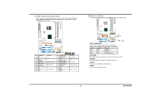
Biostar T-Series Digital Audio-out Connector: JSPDIF_OUT This connector allows users to connect the PCI bracket SPDIF output header. Pin Assignment 1 +5V 2 SPDIF OUT 3 Ground JSPDIF_OUT Codec BIOS 3 1 Front Panel Audio-out Header: JAUDIO2 This connector will allow user to connect with the front audio output headers on the PC case. It will disable the output on back panel audio connectors. Pin Assignment 1 MIC-in/ Stereo MIC-in R 2 Ground 3 Stereo MIC-in L 4 Audio power 5 Right line-out/ Speaker-out Right. 6 Right line-out/ Speaker-out Right JAUDIO2 1 2 7 Reserved 8 Key 9 Left line-out/ Speaker-out Left 10 Left line-out/ 13 14 Speaker-out Left 11 Right line-in (optional) 12 Right line-in (optional) Codec BIOS 13 Left line-in (optional) 14 Left line-in (optional) 8 TForce4/ TForce4 U Power Source Header for 1394 Chip: J1394PWR1 3 1 Pin 1-2 Close: +3.3V for 1394 chipset (default). 3 1 J1394PWR1 31 Pin 2-3 Close: +3.3V SB for 1394 chipset. Codec BIOS Header for 1394A Firewire Port at Front Panel: J1394A1 This header allows user to connect the front 1394 port for digital image devices. Pin Assignment 1 A+ 2 A3 Ground 4 Ground 5 B+ 6 B7 +12v 8 +12V 9 Key 10 Ground Codec BIOS J1394A1 9 1 10 2 User's Manual
-
 1
1 -
2
-
3
-
4
-
 5
5 -
 6
6 -
 7
7 -
 8
8 -
 9
9 -
 10
10 -
 11
11 -
 12
12 -
 13
13 -
 14
14 -
 15
15 -
16
-
17
-
18
-
19
-
20
-
21
-
22
-
23
-
24
-
25
-
26
 |
 |
