Bosch 16176 Operating Instructions
Bosch 16176 - Electronic Variable Speed Router Motor Manual
 |
UPC - 000346311600
View all Bosch 16176 manuals
Add to My Manuals
Save this manual to your list of manuals |
Bosch 16176 manual content summary:
- Bosch 16176 | Operating Instructions - Page 1
Using Lire avant usage Leer antes de usar Operating/Safety Instructions Consignes de fonctionnement/sécurité Instrucciones de funcionamiento y seguridad for Consumer Information & Service Locations Pour obtenir des informations et les adresses de nos centres de service après-vente, appelez ce - Bosch 16176 | Operating Instructions - Page 2
! WARNING Read all safety warnings and all instructions. Failure to follow the warnings and instructions may result in electric shock, fire and/or power tool. Keep cord away from heat, oil, sharp edges or moving parts. Damaged or entangled cords increase the risk of electric shock. When operating - Bosch 16176 | Operating Instructions - Page 3
accessories and tool bits etc. in accordance with these instructions Service Have your power tool serviced by a qualified repair person using only identical replacement parts. This will ensure that the safety of the power tool is maintained. Safety Rules for Routers and guiding the tool motor can - Bosch 16176 | Operating Instructions - Page 4
lay the tool down until the motor has come to a complete standstill. The spinning bit can grab the surface and pull the tool out of your control. Never use bits that have a cutting diameter greater than the opening in the base. The rated speed of the accessory must be at least equal to the - Bosch 16176 | Operating Instructions - Page 5
Router Table Read and understand the tool manual and these instructions for the use of this table with your router. Failure to follow all instructions listed cutting diameter that support shims will help maintain stability. When the table Bosch replacement parts. Any others may create a hazard. -5- - Bosch 16176 | Operating Instructions - Page 6
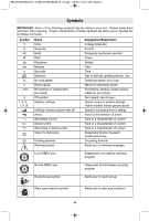
... I, II, III, 0 Name Volts Amperes Hertz Watt Kilograms Minutes Seconds Diameter No load speed Rated speed Revolutions or reciprocation per minute Off position Selector settings recycling program Read manual symbol Alerts user to read manual Wear eye protection symbol Alerts user to - Bosch 16176 | Operating Instructions - Page 7
Standards Association. This symbol designates that this tool is listed by the Canadian Standards Association, to United States and Canadian Standards. This symbol designates that this tool is listed by the Intertek Testing Services, to United States and Canadian Standards. This symbol designates - Bosch 16176 | Operating Instructions - Page 8
LEVER MOTOR HOUSING MOTOR ALIGNMENT ARROW BASE TYPE S ROUND HANDLE SUB-BASE BIT ROTATION ARROW SPEED CONTROL DIAL Models 1617EVS & 1618EVS only POWER ON/OFF SWITCH AIR VENTS BASE TYPE D REVERSIBLE HANDLE CHIP DEFLECTOR TEMPLET GUIDE QUICK CHANGE LEVER (Not included, available as accessory) FIG - Bosch 16176 | Operating Instructions - Page 9
for use with these router motors: 1617 router motor (16171) 1617EVS router motor (16176) 1618EVS router motor (16186) RA1162 D-handle router base marked type "D" is designed only for use with these router motors: 1618EVS router motor (16186) RA1166 plunge router base marked type "P" is designed - Bosch 16176 | Operating Instructions - Page 10
accessories. INSTALLING A ROUTER BIT Place router upside down or lay router on its side with the base resting on the bench. Another option is to remove the motor from the base shaft with a tissue or fine brush. The collet chuck is made up of two component parts as illustrated (Fig. 5); check to - Bosch 16176 | Operating Instructions - Page 11
gently pull it free of base. To remove motor from plunge base: (Fig. 7) 1. Hold router in horizontal position, open base clamp lever, and pull motor upwards until it stops. 2. Turn motor counter-clockwise, and gently pull it free of base. INSTALLING MOTOR IN BASE The motor can be installed with the - Bosch 16176 | Operating Instructions - Page 12
base's chip shield can also be flipped out. FIG. 9 Operating Instructions FIG. 10 FINE ADJUSTMENT DIAL INDICATOR RING CAST INDICATOR MARKS COARSE ADJUSTMENT LEVER B A BASE CLAMP LEVER Bosch routers . Your router also features three horizontal notches on both sides of the motor housing for - Bosch 16176 | Operating Instructions - Page 13
When the router is installed in a router table, it can be adjusted with a 1/8" hex wrench, not included with all models. (See page 21). The RA1002 Fine Adjustment Control Extension, an optional accessory for the non- plunge bases, allows fine adjustment from beyond the top of the motor housing. To - Bosch 16176 | Operating Instructions - Page 14
1. With the bit installed, gently lower the motor until the tip of the router bit just contacts the level surface the router is sitting on. This is the "zero" The RA1166 plunge base is equipped with a fine adjustment system that allows you to micro adjust the plunge depth of the router bit for - Bosch 16176 | Operating Instructions - Page 15
tool can be turned "ON" or "OFF" by the rocker switch located on the motor housing. One side of the switch is marked "I" for "ON", and the other side tops, smaller diameter bits and 6 25,000 cutters CONSTANT RESPONSE™ CIRCUITRY (Models 1617EVS & 1618EVS only) The router's Constant Response™ - Bosch 16176 | Operating Instructions - Page 16
grooving or dadoing, it is often necessary to guide the tool in a line parallel to a straight edge. One method of obtaining a straight cut is to securely clamp a board or other straightedge to the work surface, and guide the edge of the router sub-base along this path (Fig. 15). FIG. 15 SECURELY - Bosch 16176 | Operating Instructions - Page 17
BASE ! WARNING Read and understand these instructions and tool manual for use of these accessories. Do not reach in area of the bit while the router dust extraction hood is designed for use with Bosch routers 1617, 1617EVS, 1618EVS and their fixed bases when the routing is done in the middle - Bosch 16176 | Operating Instructions - Page 18
time as any other dust extraction hood. This dust extraction hood (optional accessory) is used for dust collection when edge-forming (Fig. 19). FIG. using two of the screw holes on the router base that are used to attach the router's sub-base. Choose the desired location for the hood. Loosen and - Bosch 16176 | Operating Instructions - Page 19
to the instructions which are included with this accessory. FIG. 22 FEED DIRECTION BASE CUT M6 WING SCREW DESIRED WIDTH WORKPIECE M6 WING SCREW FINE ADJUSTMENT INDICATOR FINE ADJUSTMENT KNOB ROUTER GUIDE RODS TEMPLET GUIDES This router can also be used with the optional Bosch-exclusive - Bosch 16176 | Operating Instructions - Page 20
PLUNGE BASE CENTERING SHAFT (optional accessory) TEMPLET GUIDE (optional accessory) D C BA D BA SUB-BASE A B CD A = M4 COUNTERSUNK SCREW HOLES B = M4 PAN-HEAD SCREW HOLES C = TEMPLET GUIDE ADAPTER SCREW HOLES D = HOLES FOR ATTACHING ROUTER TO ROUTER TABLE MOUNTING PLATE (Under sub-base on non - Bosch 16176 | Operating Instructions - Page 21
BIT/CUTTER SIZE FOR TEMPLET GUIDES When using a templet guide, use only router bit with cutters that are 1/16" less than the internal diameter of the templet guide, such as in the table below. USE WITH THREADED TEMPLET GUIDES Also available as an optional accessory is an additional adapter, the - Bosch 16176 | Operating Instructions - Page 22
9:21 AM Page 22 The undertable base accessory includes the screws needed to fasten the base to a router table mounting plate, as well as a T-hex wrench for above-table depth adjustment. ATTACHING BASE TO MOUNTING PLATE Attach the RA1161 to the router table's mounting plate using either or both sets - Bosch 16176 | Operating Instructions - Page 23
dependable service. To maintain peak efficiency of the motor, we recommend every two to six months the brushes be examined. Only genuine Bosch replacement brushes ! CAUTION Certain cleaning agents and solvents damage plastic parts. Some of these are: gasoline, carbon tetrachloride, chlorinated - Bosch 16176 | Operating Instructions - Page 24
Adjustment Control Extension ** Undertable Base with Fine Adjustment Control Extension ** Router Tables ** Quick-Release Templet Guides ** Templet Guide Adapter ** Adapter for Standard-Style Templet Guides ** Adjustable Depth Stop Turret ** (*= standard equipment) (**= optional accessories) -24- - Bosch 16176 | Operating Instructions - Page 25
BM 2610018532 01-12:BM 2610018532 01-12.qxp 1/23/12 9:21 AM Page 25 Avertissements généraux concernant la sécurité des outils électroportatifs ! AVERTISSEMENT Veuillez lire tous les avertissements et toutes les consignes de sécurité. Si l'on n'observe pas ces avertissements et ces consignes de sé - Bosch 16176 | Operating Instructions - Page 26
embouts d'outil, etc. conformément à ces instructions, en tenant compte des conditions de travail et votre outil électroportatif par un agent de service qualifié n'utilisant que des pièces de d'autres moyens pratiques de brider ou de supporter la pièce sur une plate-forme stable. Tenir la pièce à - Bosch 16176 | Operating Instructions - Page 27
érieur à celui de l'ouverture pratiquée dans la base. La vitesse nominale de l'accessoire doit être au autres moyens pratiques de brider ou de supporter la pièce sur une plate-forme stable. Tenir la pièce par un Centre de service usine de Bosch ou par une Station service agréée de Bosch. Les travaux à - Bosch 16176 | Operating Instructions - Page 28
à base de table), la pièce déformée ou tordue risque de rouler et de causer une perte de contrôle. Il y a risque de rebond et de blessures corporelles graves. Utilisez le guide réglable pour les toupillages droits. Lors du toupillage le long d'un chant d'une pièce, le guide et le coin de support - Bosch 16176 | Operating Instructions - Page 29
BM 2610018532 01-12:BM 2610018532 01-12.qxp 1/23/12 9:21 AM Page 29 Symboles IMPORTANT : Certains des symboles suivants peuvent être utilisés sur votre outil. Veuillez les étudier et apprendre leur signification. Une interprétation appropriée de ces symboles vous permettra d'utiliser l'outil de fa - Bosch 16176 | Operating Instructions - Page 30
é par l'Association canadienne de normalisation selon les normes des États-Unis et du Canada. Ce symbole signifie que cet outil est approuvé par Intertek Testing Services selon les normes des États-Unis et du Canada Ce symbole signifie que cet outil se conforme aux normes mexicaines NOM. -30- - Bosch 16176 | Operating Instructions - Page 31
FIG. 1 1617EVS INTERRUPTEUR À BASCULE MARCHE/ARRÊT LEVIER DE SERRAGE DE BASE BOÎTIER DU MOTEUR FLÈCHE D'ALIGNEMENT DU MOTEUR EMBASE DE TYPE S ROTATION DE FER -31- DÉFLECTEUR DE COPEAUX LEVIER DE CHANGEMENT RAPIDE DE GUIDE DE GABARIT (Non fourni, disponible à titre d'accessoire) FIG. 2 1618EVS - Bosch 16176 | Operating Instructions - Page 32
type 'S' est conçue pour fonctionner avec ces moteurs de défonceuse : No 1617 : Moteur de défonceuse (16171) No 1617EVS : Moteur de défonceuse (16176) No 1618EVS : Moteur de défonceuse (16186) L'embase de défonceuse à poignée en 'D' RA1162 marquée type 'D' est conçue pour fonctionner uniquement avec - Bosch 16176 | Operating Instructions - Page 33
CLÉ POUR ARBRE Pour serrer ou desserrer l'écrou de fixation de la douille, saisissez les deux clés d'une main et comprimez-les. ! AVERTISSEMENT Si le guide de gabarit est enlevé de l'embase, n'utilisez pas de fers de défonceuse d'un diamètre supérieur à 2 po car ils ne passeraient pas par le - Bosch 16176 | Operating Instructions - Page 34
. 7. Réglez la profondeur finale comme décrit dans les « instructions d'utilisation ». Pour installer le moteur dans une embase plongeante : DE RÉGLAGE GROSSIER LEVIER DE SERRAGE DE BASE LEVIER 5. Enfoncez le moteur à fDonEdSdEaRnRsAl'GemE base. 6. Serrez le levier de bridagDeEdeBAl'eSmEbase. - Bosch 16176 | Operating Instructions - Page 35
. 9 CADRAN DE RÉGLAGE DE PRÉCISION ANNEAU INDICATEUR MARQUES INDICATRICES MOULÉES LEVIER DE RÉGLAGE GROSSIER B LEVIER DE SERRAGE A DE LA BASE Les défonceuses Bosch sont conçues pour faire aisément du travail rapide et précis en ébénisterie, toupillage, moulurage de cannelures, baguettes, anses - Bosch 16176 | Operating Instructions - Page 36
réglage fin, ce qui permet à l'utilisateur de commencer le réglage à partir de n'importe quelle position de référence. Lorsque la défonceuse est installée sur une table de défonceuse, elle peut être ajustée à l'aide d'une clé à six pans de 1/8 po, qui n'est pas incluse avec tous les modèles. (Voir - Bosch 16176 | Operating Instructions - Page 37
la tourelle de profondeur au choix sur des butées progressivement plus basses jusqu'à ce que la profondeur finale (butée la plus basse ou surface plate de la tourelle) soit atteinte. Les butées sont échelonnées en hauteur tous les 1/8 po. Pour vous assurer que vos réglages de profondeur sont - Bosch 16176 | Operating Instructions - Page 38
BM 2610018532 01-12:BM 2610018532 01-12.qxp 1/23/12 9:21 AM Page 38 Pour diminuer la profondeur de manière micrométrique, abaissez la molette de réglage fin en la tournant en sens horaire de la valeur désirée. Remarques : • Quand on effectue un réglage micrométrique de la profondeur de plongée, il - Bosch 16176 | Operating Instructions - Page 39
courts possibles qui produisent la coupe désirée afin de minimiser le battement et les vibrations du fer. GUIDAGE DE LA DÉFONCEUSE La défonceuse peut être guidée dans la pièce de plusieurs manières. La méthode que vous utiliserez dépendra bien entendu de la tâche à effectuer et de ce qui semble - Bosch 16176 | Operating Instructions - Page 40
CAPUCHON D'EXTRACTION DE POUSSIÈRE POUR LE CÔTÉ ARRIÈRE DE LA BASE FIXE ! AVERTISSEMENT Veuillez lire et comprendre ces consignes et le mode d' . Ce capuchon d'extraction de poussière est conçu pour les défonceuses Bosch 1617, 1617EVS, 1618EVS et leurs embases fixes pour toupiller au milieu de - Bosch 16176 | Operating Instructions - Page 41
et 21). FIG. 19 CHANT DE LA PIÈCE CAPUCHON D'EXTRACTION DE POUSSIÈRE SOUS-EMBASE DE LA DÉFONCEUSE VIS M4 x 16mm FIG. 21 OTHER BASES FIG. 20 PLUNGE BASE VIS M4 x 16mm VIS M4 x 16mm CAPUCHON D'EXTRACTION DE POUSSIÈRE SUB - Bosch 16176 | Operating Instructions - Page 42
toupie peut également être utilisée avec le système de gabarit de guidage à changement rapide en option, une autre exclusivité Bosch, qui saisit fermement les guides dans un anneau à ressort. À la différence des gabarits de guidage conventionnels, il n'y a pas d'anneau fileté qui risquerait de se - Bosch 16176 | Operating Instructions - Page 43
la manière désirée. (Fig. 25) FIG. ADAPTATEUR DU GUIDE DE GABARIT (accessoire en option) VIS DE MONTAGE CENTRAGE DU SUPPORT DE LA BASE OU DES GABARITS DE GUIDAGE Votre toupie incorpore le modèle de centrage de précision de Bosch. Le support de sa base est centré de façon précise à l'usine. Ceci - Bosch 16176 | Operating Instructions - Page 44
centrage. 6. Appuyez légèrement sur le cône de centrage vers l'intérieur du support de la base ou du gabarit de guidage pour le centrer. 7. Serrez les vis à tête , Bosch offre en option l'embase de montage sous table RA1165 (Fig. 28). Cette embase est conçue pour être montée sous votre table de - Bosch 16176 | Operating Instructions - Page 45
instructions complètes relatives au fonctionnement d'une défonceuse en table de toupillage, ainsi qu'une clé à six pans à manche en T pour effectuer un réglage de la profondeur au-dessus de la table tables de toupillage Bosch, le sens d'avance correct est également indiqué sur le boîtier du guide - Bosch 16176 | Operating Instructions - Page 46
ou tous les deux changements de balais, il est conseillé de faire remplacer les paliers par un centre de service d'usine Bosch ou une station service agréée Bosch. Si les paliers commencent à faire du bruit (à cause de surcharges importantes ou du toupillage de matériaux très abrasifs - Bosch 16176 | Operating Instructions - Page 47
Rallonge de commande de réglage fin ** Embase de montage sous table avec rallonge de commande de réglage fin ** Tables de toupillage ** Guides de gabarit à déverrouillage rapide ** Adaptateur de guide de gabarit ** Adaptateur pour guides de gabarit de type standard ** Tourelle à butée de profondeur - Bosch 16176 | Operating Instructions - Page 48
BM 2610018532 01-12:BM 2610018532 01-12.qxp 1/23/12 9:22 AM Page 48 Advertencias generales de seguridad para herramientas mecánicas ! ADVERTENCIA Lea todas las advertencias de seguridad y todas las instrucciones. Si no se siguen las advertencias e instrucciones, el resultado podría ser sacudidas - Bosch 16176 | Operating Instructions - Page 49
que el cortador entre en contacto con su propio cable de alimentación. Si se corta un cable que tenga corriente, se puede hacer que las partes metálicas de la herramienta eléctrica que estén al descubierto tengan corriente y causen una descarga eléctrica al operador. Use abrazaderas u otro modo pr - Bosch 16176 | Operating Instructions - Page 50
el arranque. El par de reacción del motor puede hacer que la herramienta se tuerza. El corte mayor que la abertura de la base. La velocidad nominal del accesorio debe ser no desmontar ninguna de sus partes, ya que los cables internos de Fábrica Bosch o una Estación de Servicio Bosch Autorizada. ! - Bosch 16176 | Operating Instructions - Page 51
mesa de fresadora Lea y entienda el manual de la herramienta y estas instrucciones para el subirse a la mesa o a su base de soporte para alcanzar dichos materiales. del reloj según se ve desde la parte de arriba de la mesa. Hacer avanzar Bosch. Todas las demás piezas pueden crear un peligro. -51- - Bosch 16176 | Operating Instructions - Page 52
órbitas, etc., por minuto Velocidad cero, par motor cero... Graduaciones de velocidad, par motor o posición. Un número más alto significa mayor de baterías de Ni-Cd Símbolo de lectura del manual Alerta al usuario para que lea el manual Símbolo de uso de protección de los ojos Alerta al - Bosch 16176 | Operating Instructions - Page 53
Association ha catalogado esta herramienta indicando que cumple con las normas estadounidenses y canadienses. Este símbolo indica que Intertek Testing Services ha catalogado esta herramienta indicando que cumple con las normas estadounidenses y canadienses. Este símbolo indica que esta herramienta - Bosch 16176 | Operating Instructions - Page 54
) Fresadoras ABERTURAS DE VENTILACION FIG. 1 1617EVS INTERRUPTOR OSCILANTE DE ENCENDIDO Y APAGADO PALANCA DE FIJACION DE LA BASE CAJA DEL MOTOR FLECHA DE ALINEACION DEL MOTOR BASE TIPO S POMANGO REDONDO SUBBASE FLECHA DE ROTACION DE LA BROCA DIAL DE CONTROL DE VELOCIDAD (Modelos 1617EVS - Bosch 16176 | Operating Instructions - Page 55
fija RA1161 marcada tipo "S" está diseñada para utilizarse con estos motores de fresadora: Motor de fresadora 1617 (16171) Motor de fresadora 1617EVS (16176) Motor de fresadora 1618EVS (16186) La base de fresadora con mango en D RA1162 marcada tipo "D" está diseñada para utilizarse solamente con - Bosch 16176 | Operating Instructions - Page 56
uno de sus lados de manera que la base esté descansando sobre el banco. Otra opción es quitar el motor de la base antes de instalar la broca. 1. Quite de vez en cuando el mandril portaherramienta con aire comprimido y limpie la parte cónica del eje del ensamblaje del inducido con una gasa o un - Bosch 16176 | Operating Instructions - Page 57
en el sentido de las agujas del reloj hasta que se detenga. 5. Empuje el motor hacia el interior de la base tanto como se pueda. 6. Asegure la palanca de fijación de la base. INSTALACIÓN DEL MOTOR EN LA BASE El motor puede instalarse con el interruptor posicionado a la derecha o la izquierda de la - Bosch 16176 | Operating Instructions - Page 58
PALANCA DE AJUSTE BASTO B PALANCA DE FIJACION DE LA BASE A Las fresadoras Bosch están diseñadas para brindar La fresadora también cuenta con con la palanca de fijación de la base orientada hacia usted. 2. Abra la palanca de fijación de la base para soltar el motor. final de la broca. -58- - Bosch 16176 | Operating Instructions - Page 59
La extensión de control de ajuste fino RA1002, un accesorio opcional para las bases que no sean de descenso vertical, permite realizar el ajuste fino desde más allá de la parte superior de la carcasa del motor. Para instalar la extensión, simplemente presione la RA1002 hacia el interior del extremo - Bosch 16176 | Operating Instructions - Page 60
de la manera siguiente: 1. Con la broca instalada, baje suavemente el motor hasta que la punta de la broca de fresadora toque ligeramente la superficie en material de desecho antes de comenzar el trabajo. AJUSTE FINO La base de descenso vertical RA1166 está equipada con un sistema de ajuste fino - Bosch 16176 | Operating Instructions - Page 61
BOTON DE "FIJACION EN ON" (Modelo 1618EVS solamente) La herramienta se enciende mediante el interruptor oscilante ubicado en la parte superior de la caja del motor tal como se ha descrito anteriormente. Ahora la herramienta puede encenderse o apagarse apretando o soltando el gatillo. La herramienta - Bosch 16176 | Operating Instructions - Page 62
9:22 AM Page 62 AVANCE DE LA FRESADORA Tal como se ve desde la parte de arriba de la fresadora, la broca gira en el sentido de las agujas profundidad de corte y la velocidad de avance se regulan para mantener el motor funcionando a alta velocidad. Haga avanzar la fresadora a una velocidad moderada. - Bosch 16176 | Operating Instructions - Page 63
MANUAL M4 CUBIERTA DE EXTRACCIÓN DE POLVO La cubierta de extracción de polvo también puede instalarse con la salida para manguera orientada hacia la parte BASE FIJA ! ADVERTENCIA Lea y entienda estas instrucciones y el manual fresadoras Bosch 1617, 1617EVS y 1618EVS, así como con sus bases fijas - Bosch 16176 | Operating Instructions - Page 64
. 19 BORDE DE LA PIEZA DE TRABAJO CUBIERTA DE EXTRACCIÓN DE POLVO SUBBASE DE LA FRESADORA TORNILLO M4 x 16mm FIG. 21 OTHER BASES SUBBASE FIG. 20 PLUNGE BASE TORNILLO M4 x 16mm TORNILLO M4 x 16mm CUBIERTA DE EXTRACCIÓN DE POLVO SUBBASE CUBIERTA DE EXTRACCIÓN DE POLVO TORNILLO M4 x 16mm -64 - Bosch 16176 | Operating Instructions - Page 65
DE LUJO (No incluida, disponible como accesorio) La guía de fresadora de lujo Bosch es un accesorio opcional que guiará la fresadora paralela a un borde recto o le DE AVANCE BASE CORTE ANCHURA DESEADA TORNILLO DE APRIETE MANUAL M6 PIEZA DE TRABAJO TORNILLO DE APRIETE MANUAL M6 INDICADOR DE - Bosch 16176 | Operating Instructions - Page 66
de plantilla, instale la subbase utilizando el dispositivo de centrado Bosch RA1151 opcional. Siga los pasos 1-8 (Fig. 26 y 27 tal y como se describe en otra parte de este manual. 2. Posicione la subbase de manera opcional) FIG. 27 OTHER BASES FIG. 26 PLUNGE BASE EJE DEL DISPOSITIVO DE CENTRADO - Bosch 16176 | Operating Instructions - Page 67
sistema de liberación rápida Bosch. Guía de plantilla Bosch RA1101 RA1103 RA1105 RA1107 RA1109 RA1111 motor puede moverse rápidamente de una base a otra, ¡sin ninguna herramienta! La palanca de fijación de suelta rápida y los controles de ajuste de profundidad deben estar orientados hacia la parte - Bosch 16176 | Operating Instructions - Page 68
la profundidad por encima de la mesa. SUJECIÓN DE LA BASE A LA PLACA DE MONTAJE Sujete la RA1161 a la placa manual de instrucciones de la mesa de fresadora. Haga avanzar SIEMPRE la pieza de trabajo de derecha a izquierda a través de la parte delantera de la broca. En las mesas de fresadora Bosch - Bosch 16176 | Operating Instructions - Page 69
diseñados para muchas horas de servicio fiable. Para mantener un rendimiento óptimo del motor, recomendamos que cada dos a seis meses se examinen las escobillas. Sólo se deben usar escobillas de repuesto Bosch genuinas diseñadas específicamente para su herramienta. RODAMIENTOS Después de 300-400 - Bosch 16176 | Operating Instructions - Page 70
y 1617EVSPK solamente) Cubierta de extracción de polvo ** Cubierta de extracción de polvo para conformado de bordes ** Extensión de control de ajuste fino ** Base para debajo de la mesa con extensión de control de ajuste fino ** Mesas de fresadora ** Guías de plantilla de suelta rápida ** Adaptador - Bosch 16176 | Operating Instructions - Page 71
BM 2610018532 01-12:BM 2610018532 01-12.qxp 1/23/12 9:22 AM Page 71 Notes: Remarques : Notas: -71- - Bosch 16176 | Operating Instructions - Page 72
or replacement of parts, without charge, which BOSCH Factory Service Center or Authorized Service Station. For Authorized BOSCH Power Tool Service Stations, please refer to your phone directory. THIS LIMITED WARRANTY DOES NOT APPLY TO ACCESSORY ITEMS SUCH AS CIRCULAR SAW BLADES, DRILL BITS, ROUTER
-
 1
1 -
 2
2 -
 3
3 -
 4
4 -
 5
5 -
 6
6 -
 7
7 -
8
-
9
-
10
-
11
-
12
-
13
-
14
-
15
-
16
-
17
-
18
-
19
-
20
-
21
-
22
-
23
-
24
-
25
-
26
-
27
-
28
-
29
-
30
-
31
-
32
-
33
-
34
-
35
-
36
-
37
-
38
-
39
-
40
-
41
-
42
-
43
-
44
-
45
-
46
-
47
-
48
-
49
-
50
-
51
-
52
-
53
-
54
-
55
-
56
-
57
-
58
-
59
-
60
-
61
-
62
-
63
-
64
-
65
-
66
-
67
-
68
-
69
-
70
-
71
-
72
 |
 |
IMPORTANT:
IMPORTANT :
IMPORTANTE:
Read Before Using
Lire avant usage
Leer antes de usar
Operating/Safety Instructions
Consignes de fonctionnement/sécurité
Instrucciones de funcionamiento y seguridad
1617
1617EVS
1617EVSPK
1618EVS
For English Version
Version française
Versión en español
See page 2
Voir page 25
Ver la página 48
1-877-BOSCH99 (1-877-267-2499)
www.boschtools.com
Call Toll Free for
Consumer Information
& Service Locations
Pour obtenir des informations
et les adresses de nos centres
de service après-vente,
appelez ce numéro gratuit
Llame gratis para
obtener información
para el consumidor y
ubicaciones de servicio
2
1
0
IN
50
40
30
20
10
0
MM
BM 2610018532 01-12:BM 2610018532 01-12.qxp
1/23/12
9:21 AM
Page 1