Bosch 16176 Operating Instructions - Page 20
Fig. 26, Plunge Base, Fig. 27, Other Bases, Fig. 25 - table
 |
UPC - 000346311600
View all Bosch 16176 manuals
Add to My Manuals
Save this manual to your list of manuals |
Page 20 highlights
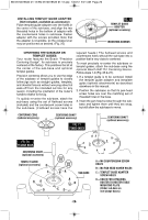
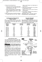
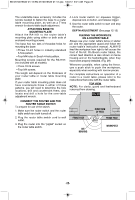
BM 2610018532 01-12:BM 2610018532 01-12.qxp 1/23/12 9:21 AM Page 20 INSTALLING TEMPLET GUIDE ADAPTER (Not included, available as accessory) Place templet guide adapter over the holes in the center of the sub-base, and align the two threaded holes in the bottom of adapter with the countersunk holes in sub-base. Fasten adapter with the screws provided. Note that the adapter is reversible, so the release lever may be positioned as desired. (Fig. 25) FIG. 25 TEMPLET GUIDE ADAPTER (optional accessory) MOUNTING SCREWS CENTERING THE SUB-BASE OR TEMPLET GUIDES Your router features the Bosch "Precision Centering Design". Its sub-base is precisely centered at the factory. This positions the bit at the center of the sub-base and optional templet guides. Precision centering allows you to use the edge of the subbase or templet guides to closely follow jigs such as straight guides, templets, and dovetail fixtures without worrying about bit walk-off from the intended cut line for any reason, including the orientation of the router's handles relative to the jig. To quickly re-center the sub-base, attach the sub-base using the set of flathead screws (included) and the countersunk screw holes in the sub-base. (Flathead screws have the tapered heads.) The flathead screws and countersunk holes will pull the sub-base into a position that is very close to centered. To most precisely re-center the sub-base or templet guides, attach the sub-base using the optional Bosch RA1151 Centering Device. Follow steps 1-8 (Fig. 26 & 27). 1. If a templet guide is to be centered, Install the templet guide adapter and template guide (optional attachments) as described elsewhere in this manual. 2. Position the sub-base so that its pan-head screw holes are over the matching set of threaded holes in the base. 3. Insert the pan-head screws through the subbase and tighten them until they are snug, but still allow the sub-base to move. CENTERING CONE (optional accessory) CENTERING SHAFT (optional accessory) FIG. 27 OTHER BASES CENTERING SHAFT (optional accessory) FIG. 26 PLUNGE BASE CENTERING SHAFT (optional accessory) TEMPLET GUIDE (optional accessory) D C BA D BA SUB-BASE A B CD A = M4 COUNTERSUNK SCREW HOLES B = M4 PAN-HEAD SCREW HOLES C = TEMPLET GUIDE ADAPTER SCREW HOLES D = HOLES FOR ATTACHING ROUTER TO ROUTER TABLE MOUNTING PLATE (Under sub-base on non-plunge bases) -20-
-
 1
1 -
2
-
3
-
4
-
5
-
6
-
7
-
8
-
9
-
10
-
11
-
12
-
13
-
14
-
 15
15 -
 16
16 -
 17
17 -
 18
18 -
 19
19 -
 20
20 -
 21
21 -
 22
22 -
 23
23 -
 24
24 -
 25
25 -
26
-
27
-
28
-
29
-
30
-
31
-
32
-
33
-
34
-
35
-
36
-
37
-
38
-
39
-
40
-
41
-
42
-
43
-
44
-
45
-
46
-
47
-
48
-
49
-
50
-
51
-
52
-
53
-
54
-
55
-
56
-
57
-
58
-
59
-
60
-
61
-
62
-
63
-
64
-
65
-
66
-
67
-
68
-
69
-
70
-
71
-
72
 |
 |
