Bosch SHV68E13UC Installation Instructions
Bosch SHV68E13UC - Accepts Custom Panels Integra 800 Manual
 |
UPC - 825225868354
View all Bosch SHV68E13UC manuals
Add to My Manuals
Save this manual to your list of manuals |
Bosch SHV68E13UC manual content summary:
- Bosch SHV68E13UC | Installation Instructions - Page 1
A _uJ €_ C_ Go Lt_ c_ C_ €_ c_ €_ - Bosch SHV68E13UC | Installation Instructions - Page 2
, OBSERVE ALL WARNINGS AND CAUTIONS. These instructions are intended for use by qualified installers only. The dishwasher must be installed by a qualified service technician or installer. , In addition to these instructions, the dishwasher shall be installed to meet all electrical and plumbing codes - Bosch SHV68E13UC | Installation Instructions - Page 3
A Avoiding General Hazards Do not use the dishwasher until it is completely installed. When opening the door on an uninstalled dishwasher, carefully open the door while supporting the rear of the unit. Failure to follow this warning can cause the dishwasher to tip over and result in serious injury. - Bosch SHV68E13UC | Installation Instructions - Page 4
14 AWG, 2 conductor, 1 ground, insulated copper conductors rated 75°C or higher. Hot Water Supply Line - Minimum 3/8" O.D. copper tubing or metal braided dishwasher supply line. Shut-off valve and fittings appropriate for hot water supply line (copper tubing/compression fitting, or braided hose). UL - Bosch SHV68E13UC | Installation Instructions - Page 5
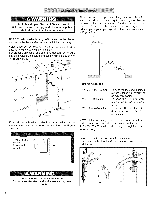
_ I_:_:i A Extra Tall Item Sprinkler (See Use and Care Manual) B Toe Panel Screws C Mounting Brackets D Mounting Bracket Screws E Toe Panel (2 pieces) F Toe Panel caps G Screw Clamp (for hose) H Water Supply Adaptor Fitting I Flexible Edge Protector Grommet for electrical wire J Rubber Drain - Bosch SHV68E13UC | Installation Instructions - Page 6
supply ar_ shut off before installation or service, j After locating the proper place for your new dishwasher, you will need to make dishwasher drain hose toward the drain con nection If the dishwasher is to be installed in a corner, make sure that there is adequate clearance to open the door - Bosch SHV68E13UC | Installation Instructions - Page 7
the parts bag to securely mount the junction box so that it can be easily accessed (see Figure 4). The electrical supply can be connected in two ways: ::'Pla1'c'°e' Id Wiring Figure 4 Electrical Supply The customer has the responsibility of ensuring that the dishwasher electrical installation is - Bosch SHV68E13UC | Installation Instructions - Page 8
junction box cover with the 4 screws. Avoid Electrical Shock Hazard To avoid possible injury or property damage, care should be exercised when the dishwasher is installed or removed to reduce the likelihood of damage to the power cord. Hot Water Supply The hot water heater should be set to deliver - Bosch SHV68E13UC | Installation Instructions - Page 9
local ordinance require an air gap, install it according to the manufacturer's instructions. If the dishwasher drain hose is to be connected to a disposer dishwasher drain connection, remove the plug from the disposer's dishwasher drain connection. The dishwasher drain hose must have one place along - Bosch SHV68E13UC | Installation Instructions - Page 10
the drain hose end. 2. Obtain the Rubber Drain HoseAdaptor spring clamp from the Dishwasher Installation Kit (do not substitute). 3. Insert the dishwasher drain hose into the end of the drain hose (see Figure 12). Be sure to fully insert the drain hose. 4. Use the clamp provided to attach the Rubber - Bosch SHV68E13UC | Installation Instructions - Page 11
Hazard Do not use the dishwasher until it is completely installed. When opening the door on an uninstalled dishwasher, carefully open the door while supporting the rear of the unit. Failure to follow this warning can result in serious injury. LEVELING THE DISHWASHER The unit should now be ready - Bosch SHV68E13UC | Installation Instructions - Page 12
to rest on the floor. 2. Position the mating front toe panel on top of the rear toe panel allowing the angled edge to rest on the mating edge of the dishwasher. 3. Drive the two black screws (included) through the hole in the toe panel to secure. Use the supplied screws to avoid damaging the - Bosch SHV68E13UC | Installation Instructions - Page 13
are havinga problem withyour dishwasher,beforecallingfor serviceplease refer to the Self Help section in the Use and Care Manual.If serviceis : 1. Contact your installer or the AuthorizedService Contractorin yourarea. 2. E-mail us. See your Use and Care Manual for instructions. 3. Writeus at the - Bosch SHV68E13UC | Installation Instructions - Page 14
a I'utilisation par un installateur qualifie seulement. Ce lave-vaisselle doit _tre installe par un technicien ou un installateur qualifie seulement. En plus de ces instructions, le lave=vaisselle doit _tre installe conformement aux codes et reglementations electriques et de plomberie (nationaux et - Bosch SHV68E13UC | Installation Instructions - Page 15
Ce lave-vaisselle doit etre relier a la terre soit en le connectant au support metallique qui est relie a la terre soit en branchant la prise du terre avec les normes nationales et regionales. Ces instructions sont relatives a une methode d'installation utilisant des tuyaux d'alimentation en acier - Bosch SHV68E13UC | Installation Instructions - Page 16
Marteau Scie-cloche F __b) Cl6 a tuyau Cl6 r6glable Ruban a mesurer Coupe-ill Tournevis & lame plate Outil & d6nuder Tournevis Phillips Tournevis -[-20 [©, Niveau C&ble d'alimentation 61ectrique - minimum #14AWG, 2 conducteurs, 1 mise a la terre, conducteurs en cuivre isol6s cot6 75 °C - Bosch SHV68E13UC | Installation Instructions - Page 17
_ I_:_:i A Bras gicleur pour grands articles B Vis du panneau inf@ieur g Fixations D Vis de fixations E Panneau inf@ieur F Vis du panneau inf@ieur G Pince & ressort (pour tuyau) H Raccord adaptateur pour alimentation en eau I Rondelle de protection flexible pour fil electrique J Fixations - Bosch SHV68E13UC | Installation Instructions - Page 18
brOlures et les chocs _lectriques. I ! S'assurer que les alimentations en eau et @lectrique I sont ferm_es avant d'effectuer rinstallation ou le| service j REMARQUE " cet appareil est congu pour etre encastr6 sur le dessus et les c6t6s par des armoires de cuisine r6sidentielle standard - Bosch SHV68E13UC | Installation Instructions - Page 19
adjacente au lave-vaisselle (ne pas les installer derriere I'appareil). II faut une ouverture dishwasher, I_viter les risques d'incendie S'assurer que les connexions _lectriques ne sont pas I_ches et qu'elles sont ad_quatement branch_es. instructions DU CANADA, C22,1, derniere edition au Canada - Bosch SHV68E13UC | Installation Instructions - Page 20
(152,4 mm) du lave-vaisselle. €:viter les risques de chocs _lectriques Pour @viter tout dommage a la propri@t@ ou des blessures, faire trCs attention au moment d'installer ou d'enlever le lave-vaisselle afin de ne pas endommager le cordon d'alimentation. 2O - Bosch SHV68E13UC | Installation Instructions - Page 21
connexion du drain du broyeur par un intervalle d'air, figure 11. REMARQUES IMPORTANTES: • Si les exigences locales requierent un intervalle d'air, installer selon les instructions du fabricant. • Si le tuyau de drain est branche sur la connexion du drain du broyeur, enlever la fiche de la connexion - Bosch SHV68E13UC | Installation Instructions - Page 22
le tuyau de drainage. Utiliser la pince fournie pour fixer I'adaptateur de tuyau de drainage en caoutchouc sur la plomberie r6sidentiel Avant d'installer la fixation de plan de travail fournie, d_cider quelle m_thode de fixation s_curitaire du lave=vaisselle sera utilis_e. Une fois les fixations - Bosch SHV68E13UC | Installation Instructions - Page 23
Avoid Tip Over Hazard Do not use the dishwasher until it is completely installed. When opening the door on an uninstalled dishwasher, carefully open the door while supporting the rear of the unit. Failure to follow 6galit6 de la surface des reliefs. For Top Mount - Wooden Figure 17 02 mm/0.1" 23 - Bosch SHV68E13UC | Installation Instructions - Page 24
19 4. Pour les modeles avec le panneau exterieur, faire glisser les fixations (A) foumies dans les fentes du panneau inf@ieur que I'on vient d'installer. REMARQUE : une fois la position des fixations determinee, enlever la fixation et plier la tanguette en metal. Voir figure 20. Ceci permet de - Bosch SHV68E13UC | Installation Instructions - Page 25
I'ordre indique ci-dessous)jusqu'a ce que le probleme soit corrige : 1. Communiquer avec I'installateur ou le centre de service dans la region. 2. Envoyer un courriel. Voir le guide d'utilisation et d'entretien pour les instructions. 3. I_crire a : BSH Home Appliances, Corp. 5551 McFadden Avenue - Bosch SHV68E13UC | Installation Instructions - Page 26
26 - Bosch SHV68E13UC | Installation Instructions - Page 27
en comercios de servicios alimenticios. INSTALACION NUEVA- Si se trata de una instalaci6n nueva de la lavadora de platos, se debe realizar la mayor parte del trabajo antes de colocar la lavadora en su lugar. REEMPLAZO- Si la lavadora de platos est_ reemplazando a otra lavadora, revise las conexiones - Bosch SHV68E13UC | Installation Instructions - Page 28
el lavaplato_es de que este totalmente instalado. Cuando abra la puerta del lavaplatos antes de ser instalado, h&galo cuidadosamente mientras detiene la parte posterior de la unidad. No seguir esta advertencia puede causar que el lavaplatos se vuelque hacia delante y ocasionar una lesi6n grave - Bosch SHV68E13UC | Installation Instructions - Page 29
Herramientas y materiales que se necesitan Martillo Sierra Cinta de medir Destornillador piano Destornillador de cruz Pinzas para cortar cables Alicates pelacables Llave ajustable Destornillador %20 Nivel Cable el6ctrico- Minimo #14 AWG, 2 hilos, 1 tierra, conductores aislados de cobre para - Bosch SHV68E13UC | Installation Instructions - Page 30
de pie C Soportes de montaje en la cubierta de trabajo D Tornillos para los soportes de montaje E Panel de pie F Tornillos del panel de pie G Abrazadera de resorte (para la manguera) H Conexi6n para el adaptador del suministro de agua I Arandela de protecci6n de borde flexible para el cable - Bosch SHV68E13UC | Installation Instructions - Page 31
antes de realizar la instalacion o dar el servicio. NOTA: Esta lavadora de platos se debe instalar de tal modo que quede cubierta en la parte superior y por los costados por gabinetes normales de cocina. Seleccione un lugar Io m_s cerca posible al fregadero para tener f_cil acceso alas tubedas de - Bosch SHV68E13UC | Installation Instructions - Page 32
dados. Use los cuatro tornillos incluidos (o sujetadores apropiados) en la bolsa de partes para fijar la caja de conexiones de modo que se tenga f_cil acceso a ) junction box and three prong plug _t_ EleacretricincclourddedwittY" 4_ith dishwasher M_todo A - Enchufe y receptaculo de tres clavijas Use - Bosch SHV68E13UC | Installation Instructions - Page 33
. NOTA: Si el lavaplatos es tapado en un z6calo el6ctrico, entre en contacto con el servicio de atenci6n al cliente para pedir el kit de accesorios aprobado del cable el6ctrico CONEXIONES DE ENTRADA DE AGUA Suministro de agua caliente El calentador de agua debe proporcionar agua a ia lavadora - Bosch SHV68E13UC | Installation Instructions - Page 34
tubeda de agua de la lavadora y conectarla a la v_lvula de cierre. Para conectar el suministro de agua caliente: 1. Instale la conexi6n del adaptador del suministro de agua de la bolsa de partes sobre la manguera de suministro de agua de la lavadora de platos (vea la Ilustraci6n 7). Esta conexi6n no - Bosch SHV68E13UC | Installation Instructions - Page 35
adaptador de hule para la manguera de desagQe y las dos abrazaderas de manguera del kit de instalaci6n que viene con la lavadora de platos (no use sustitutos). 2. En un puerta cuidadosamente mientras seporta la parte trasera de la unidad. Si no observa esta advertencia podria sufrir lesiones serias - Bosch SHV68E13UC | Installation Instructions - Page 36
patas niveladoras delanteras insertando los dos tornillos de fijaci6n que se inchyen para estas patas niveladoras en los dos refuerzos ubicados en la parte delantera de los niveladores. Vea la Ihstraci6n 18. 3. Apriete los tornillos hasta que queden al ras con la superficie de los refuerzos. Para - Bosch SHV68E13UC | Installation Instructions - Page 37
introducir mas de lo que se necesita. 5. Vuelva a insertar los soportes. 6. Instale el panel de pie exterior en los soportes y apriete los tornillos incluidos para fijar el panel de pie. NOTA: La pieza de goma debe permanecer detr_s de la parte inferior del panel exterior. Figure 19 , Figure 20 37 - Bosch SHV68E13UC | Installation Instructions - Page 38
su entera satisfacci6n: 1. Contacte a su instalador o al contratista de servicio autorizado en su area. 2. Mandenos un correo electr6nico. Consulte su manual de uso y cuidado para las instruc= ciones. 3. Escribanos a la siguiente direcci6n: BSH Home Appliances, Corp. 5551 McFadden Avenue Huntington - Bosch SHV68E13UC | Installation Instructions - Page 39
9000373537RevA - 02/25/09 39
-
 1
1 -
 2
2 -
 3
3 -
 4
4 -
 5
5 -
 6
6 -
 7
7 -
8
-
9
-
10
-
11
-
12
-
13
-
14
-
15
-
16
-
17
-
18
-
19
-
20
-
21
-
22
-
23
-
24
-
25
-
26
-
27
-
28
-
29
-
30
-
31
-
32
-
33
-
34
-
35
-
36
-
37
-
38
-
39
 |
 |

A
_uJ
€_
C_
Go
Lt_
c_
C_
€_
c_
€_