Bose 201 Loud Owner's guide - Page 2
Placement, Selection
 |
View all Bose 201 Loud manuals
Add to My Manuals
Save this manual to your list of manuals |
Page 2 highlights
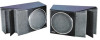
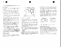
• • • The Bose 201 Direct/Reflecting' Loudspeaker System 1. Introduction Thank you for purchasing the Bose 201 DirecVReflecting' Loudspeaker System. Its advanced design and quality construction will give youmany years of listening pleasure. The installation and operating principles of your 201 system are significantly different from those of conventional speaker systems. To obtain the best possible performance, please take the time to read this manual. 2. Unpacking The shipping carton contains two 201 speakers labeled Part1(left)and Part 2 (right). Unpack each unit carefully. saving the carton and all packaging materials for later use. If either speaker appears to be damaged when unpacking, do not operate the damaged unit Repack both speakers in their original canon and notify your authorized Bose dealer immediately. Do not attempt to remove the foam grille panels or "Bose" nameplates on your 201 Loudspeakers. This can result in damage riot covered by the warranty. 3. Placement 201 Loudspeakers are designed for convenient placement in a wide variety of listening environments. They can be set on bookshelves and tables or (lush-mounted directly onto a wall. If you are placing your 201 speakers on a shelf or table, attach the self-adhesive rubber feet supplied in the shipping carton to the bottom of the speaker enclosures. If you are wall-mounting your 201 speakers, obtain a set of Bose 201 Wall Brackets from your authorized Bose HighFidelity dealer. Complete instructions are included with the brackets. The following placement guidelines will help you to reakze the best possible performance from your 201 speakers in . any type of installation. Refer to FIGURE 1. CEiLiNG \\* I I-3 feel (3)- 90cm) IMn'murn Winches (Can) u.• LefrPSapteak./ 4-12 face O 0.2-3.6m1 Pan 2 A Firjl Speaker BACK WALL klnimum Winches KS an) FLOOR FIGURE 1. Recommended placement in average-sized listening rooms. a. Your 201speakers work best whenmusic is given space to develop "around" the cabinet& reflecting off nearby walls to create a wide, transparent stereo image. Hard materials such aswood, brick, glass. sheetrock and/or sturdy paneling generally provide the most effective sound-reflecting surfaces. Sound-absorbent furnishings (heavy drapes, etc.) should be kept away from the immediate vicinity of the speakers. b. Place the Part1and Part 2 speakers on the left and right sides of the room respectively, spaced 4-12 feet (1.2-3.6 m) apart. Vertical placement (with the energy controls facing directly upward or downward) is not recommended. c. Position the speakers at least 12 Inches (30 cm) away from the side walls. Optimum distance is112/ -3 feet (45-90 cm). d The most accurate bass response results when the speakers are set less than 18 Inches (45 cm) away from the wall behind them, and more than18 inches from the floor or ceiling. Avoid placing the speakers exactly halfway between the floor and ceiling. c. If your music seems to be lacking in deep bass, try moving the speakers closer to the wall behind them and/ or nearer to the corners of the listening room. Heavy. "booming" bass can be tamed by moving the speakers away from corners and walls. You can also experirnei with the tone controls on your amplifier or receiver to achieve a spectral balance that suits your listening environment and personal tastes. 4. Wire Selection Audible coloration of the sound and/or power loss will occur if the wire comecting the speakers to your amplifier or receiver is too small. The table below specifies the minimum thickness of 2-conductor wire recommended for various speaker-to-amp distances. RECOMMENDED WIRE SIZES* Maximum Length Wire Gauge 30 feel( 9m) 18 (0.75 innil 45 leet (14 m) 16(1.5=12) 70 feet (21 m) 14 (2 0 mmw) 'Based on a maximum frequency response deviation ol•.05 dB. Standard 2-conductor zipcord (available al electrical and hardware stores) can be used for speaker connection. This wire is often color-coded, or else has a ribbed line(s) ruining along one conductor for easy identification of the positive and negative leads.
-
 1
1 -
 2
2 -
 3
3 -
 4
4
 |
 |
