Bose 201 Loud Owner's guide - Page 3
Connection, Phasing, Fusing, Direct
 |
View all Bose 201 Loud manuals
Add to My Manuals
Save this manual to your list of manuals |
Page 3 highlights
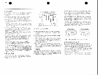
. . • 5. Connection Follow the next procedure to assure that both 201 speakers are properly connected to your music system. Refer to FIGURE 2. a. Turn off your amplifier or receiver and unplug it from the ac power mains before connecting the loudspeakers. b. Separate the conductors at the end of each length of wire. Strip approximately Y2 inch (12 mm) of insulation off each conductor. c. Locate the input terminals on the back of the left speaker cabinet. Note that there are two terminals marked + (posi- tive) and - (negative). d. Connect one wire conductor to the terminal marked - on the left speaker. Connect the other end of the same conductor to the output terminalmarkedCOM, GND, NEG or - on the left channel of your amplifier. Use the color•coding or ribbed line(s) on the wire to be sure you are using the same conductor. e. In the same manner, connect the + terminal on the left speaker to the output terminal masked POS or + on the left amplifier channel. (If your amplifier otters a choice of output impedances, use the terminal marked 8 or 8 OHMS.) f. Repeat steps 4 and 5 above. connecting the right speaker to the right output channel of your amplifier. Tighten all terminal connections firmly. g. Check very carefully to be certain that no loose strands of wire are accidentally "bridged' across the terminals on either the speakers or the amplifier. Bridged wires create short circuits which can damage your amplifier. Repair any bose wire strands before operating your amplifier or receiver. 6. Phasing Test If you are not certain that the speakers are connected to your amplifier "in phase" (i.e.. positive to positive. negative to negative), perform this simple test: STEREO AMPLIFIER OR RECEIVER Left Output I I Right Output 1.5A1 + - Pall Leff Speaker Pert 2 ng1A Speaker 'Optisnal 1.5-ampere. last-01ow fuse (See Section7) FIGURE 2. Speaker connection. a. Set your sound system for MONO (monophonic) reproduction. Be sure the balance control is centered or set to normal. b. Temporarily place the loudspeakers so that they are facing each other closely. c. Play music containing deep bass notes through the system. If the speakers are phased correctly, the sound will appear to come from a point between the speakers with full, natural bass response. d. II the music seems to be lacking in deep bass. reverse the + and - wire connections on one speaker and repeat the test. Use the connection that produces the most powerful bass. 7. Fusing Any loudspeaker can be damaged if the amplifier driving it should fait. Damage may also occur by playing the music so loudly that it sounds distorted. This can happen even with a low-powered amplifier or receiver. Your 201 speakers incorporate an automatic tweeter protection circuit which guards against certain types of electrical stress. Fusing will provide additional protection. and is recommended inmost applications. The fuseholders should be inserted into the + wire connecting each speaker to your amplifier or receiver (see FIGURE 2). Use 1.5-ampere, fast-blow Buss AGC Series. Littelluse 3AGSeriesor equivalent fuses. A complete fuse k4 including fuses and holders is available from the Bose Customer Service Department. The Mountan. Framingham. Massachusetts USA 01701 for $5.00. Ask for the 201 Fuse Kit. Part Number 108938-4 maRimoleadme cretodaocmtesdestaatnt Pau 1 Spiralus 5 3 Pctale courted:alma. la maximumrateflaclsourd. Pant ROI 820210x 4 FIGURE 3. Operation of the Direct Energy Controls. 8. Direct Energy Control The Direct Energy Control lets you change the balance of reflected and direct sound radiated by your 201 speakers to fit virtually any type of placement or music. Its audible ellect depends on your distance from the speakers and the acoustics of your listening room. In most cases. proper adjustment of the Direct Energy Controls will significantly improve the performance of your 201 system. Note that the numbers shown in FIGURE 3 are for reference purposes only and do not actually appear on the speakers.
-
 1
1 -
 2
2 -
 3
3 -
 4
4
 |
 |
